Technical data are subject to change without notice.
© Copyright SPM 2002-04. 71650.B
SPM Instrument AB • Box 504 • S-645 25 Strängnäs • Sweden
Tel +46 152 225 00 • Fax +46 152 15075 • info@spminstrument.se • www.spminstrument.se
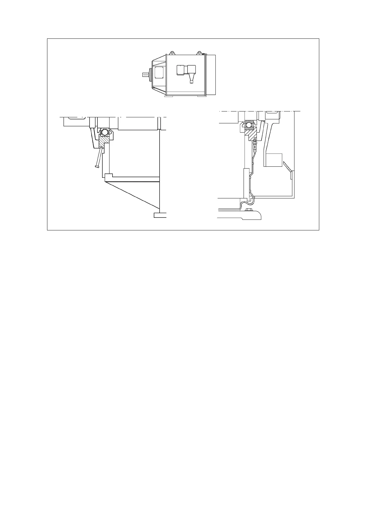
Measuring points, examples
On large electric motors, the bearings are often mounted in bushings which are welded or bolted
to the motor shields. Because of the damping in the interface between the bushing and the shield,
the measuring point should be on the bushing.
The bearing bushing at the drive (A) end is usually within reach. A long adapter is installed at an
angle to the shield, so that there is enough space for connecting the transducer.
Installed transducer
The bearing at the fan end (B) requires a permanent transducer installation. The transducer is
installed in the bushing. The coaxial cable is run through a slit in the fan cover to a measuring
terminal on the stator frame.
Check installed equipment
Incorrectly installed adapters or transducers can cause a significant damping of the shock pulse
signal.
Check all installations. Make sure that mounting holes are correctly countersunk and that the seat
surfaces of adapters have good contact with the material of the bearing housings.
Any metallic machine part knocking or rubbing against the adapter will produce a disturbance. This
must be avoided by making large clearance holes and using soft, elastic sealing material.
Use high temperature cables and moisture proof equipment where required, and protect installa-
tions against damage. Adapters should be fitted with protecting caps.
Mark the measuring points
Measuring points for the probe transducer should be clearly marked with SPM measuring point
markers. To get comparable readings, one must always use the same measuring point.
A
drive end
A
B
B
fan end
16 SPM measuring points and transducers