Instruction Manual
for
AS380 Series Elevator Integrated Drive Controller
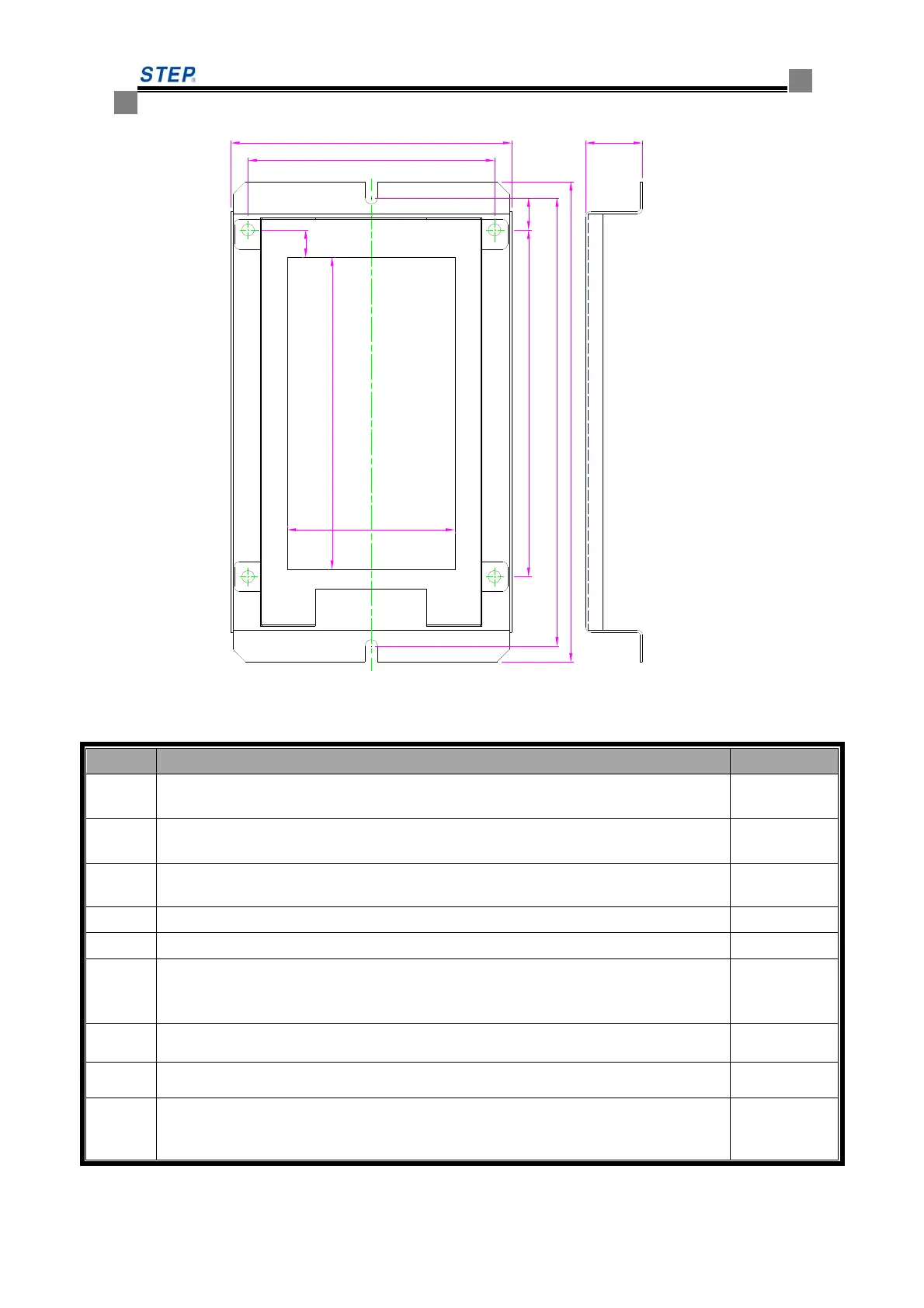
122
140
194
100
114
181
23
126
68
11
13
Fig 6.26 SM-04-VL/B3 installation dimension
Table 6.16B SM-04-VL/B3 plug-in specification and port definition
Serial Descriptions Remarks
JP1
Serial port, of which Pin 1 for TXV+, Pin 2 for TXV-, Pin 3 for TXA+ and Pin 4 for
TXA- respectively.
CH3.96-4
JP3
Up-call terminals, of which Pin 1- and Pin 2+ for button indicator, Pin 3 and Pin 4
for button input.
CH2510-4
JP4
Down-call terminals, of which Pin 1- and Pin 2+ for button indicator, Pin 3 and Pin 4
for button input.
CH2510-4
JP5
Pin 3 and Pin 4 of JP5 connected to the normal open contact of elevator –lock switch CH2510-4
JP6
Pin 3 and Pin 4 of JP6 is the port for passenger button CH2510-4
SW2
The dip switch of serial communication terminal resistor , right turn mean the
connection of built-in 120Ω resistor
SW1.2
SW1.2 ON for display in English, OFF for display in Chinese and English together.
SW1.3
SW1.3 OFF in standard mode
SW1.4
SW1.4 ON for setting address codes of the display board, and SW1.4 OFF after
setting finished.
 Loading...