Instruction Manual
for
AS380 Series Elevator Integrated Drive Controller
203
downward leveling on each floor, such as up higher down lower, or up lower down high,
make leveling adjustment of Parameter F56, F57 in the parameter menu. Its default value is
50mm. decrease this value for up higher down lower, and increase this value for up lower
down higher, by the adjustment amount of half of the leveling difference. For example: the
total difference for up higher down lower is 20mm and then decrease this value by 10mm.
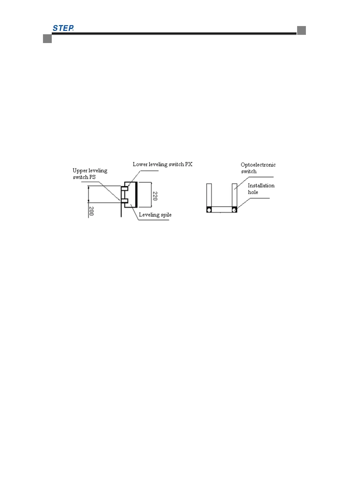
◆ Installation standard for leveling switch:
When the lift car sill and the hall door sill keep the absolute level, the upper surface of the
leveling spile is about 10mm higher than the lower leveling switch, and the lower surface of the
leveling spile is about 10mm lower than the upper leveling switch, which facilitates the
adjustment of comfort and leveling accuracy. The standard length of leveling spile is 220mm to
ensure that every spile is of the same length (the length error should be less than 3mm). (See
Diagram 8.5)
Diagram 8.5 Installation standard for leveling switch
⑴ Select magnetic switch as leveling switch:
①Insert the leveling switch into the leveling spile deep enough to ensure that the action of
leveling switch is effective and reliable;
②The verticality of the leveling spile is very demanding to ensure that it will not happen for
leveling stop that only one leveling switch acts effectively, but the other has run out of
effective motion range, which will affect the normal operation of elevator.
⑵ Select optical switch as leveling switch (our company generally accepts low-level effective
signal for the input interface of the serial system):
Follow the following points to gain a better effect:
① Scrape the paint in the shadow around the installation hole, to guarantee that the metal shell is
well grounded by photoelectric switch bolts, brackets and car top; if press an earthing wire
under the mounting bolt after scrape, and connect it to the earthing pile of the connection box
on the car top, the effect will be better;
② Photoelectric switch should be connected to the connection box on the car top, and ground
the shield layer;
③ Photoelectric switch should use normal open switch, to reduce interference of photoelectric
switch itself.
④ The photoelectric switch flashing in operation may cause exception for elevator operation or
leveling, then it may be subject to interference, so connect a capacitor of 0.1μF63V between
the photoelectric switches COM and PS (or PX). (See Diagram 8.6)
 Loading...