Instruction Manual
for
AS380 Series Elevator Integrated Drive Controller
204
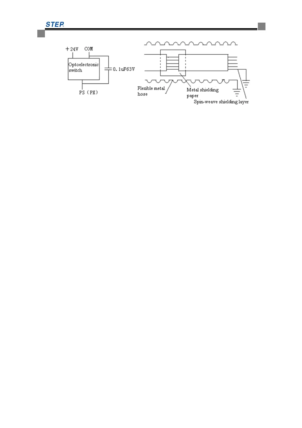
Figure 8.6 Capacitor connection diagram
Note: improper dispose of leveling photoelectric switch may interfere with normal operation,
and frequent change is not a fundamental solution, and will greatly increase the cost. Taking the
above 4 methods will greatly reduce the interference and even eliminate interference.
◆Notes for leveling switch installation
① The optical switches or magnetic switches should be inserted to 2 / 3 of the leveling spile, and
check the leveling spile on each floor should be vertical and the insertion depth should be the
same.
② After the optical switches or magnetic switches inserted into the leveling spile, ensure that
both ends expose 10mm-30mm, as shown below:
③ During installation, Keep the spile center on each floor is along the same line with the sensor
center, which will guarantee the leveling effect.
④ When the elevator goes upward and downward respectively and arrives at every floor normally,
record the height difference between the lift car sill and the hall door sill. When the elevator runs
up: lift car sill higher means leveling excess, otherwise means leveling lack; when the elevator
runs down: lift car sill lower means leveling excess, otherwise means leveling lack. After
recording, move the unleveling well spile, and record again after moving.
If the leveling difference is considerable for each floor, adjust the leveling spiles to set them to the
same deviation. Take this as reference, and debug parameters to control these leveling deviations
within the standard scope.
 Loading...