Instruction Manual
for
AS380 Series Elevator Integrated Drive Controller
49
equipment technical standards. Moreover, the grounding line should be as short as possible. If the
distance between the grounding line and the earth point is too far, the electricity leakage of
integrated drive controller may cause the instability of the electric potential of grounding terminal.
d) Grounding line should adopt the multi-strand copper core line with diameter of 3.5mm
2
. It is
recommended to use specialized yellow-green grounding line.
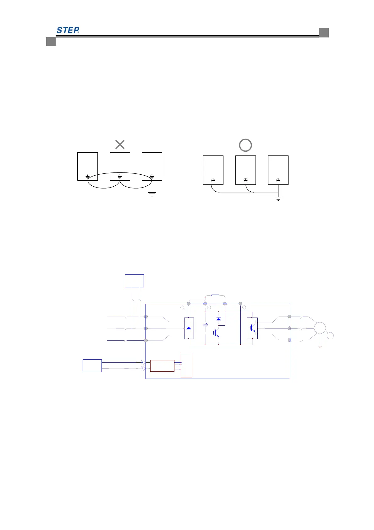
e) When several elevator integrated drive controller is grounded. It is recommended not to
arrange the wires into loop. The detailed grounding method for several elevator integrated drive
controllers is as the fig 4.5
Fig 4.5 multi-elevator integrated drive controllers wiring
4.4.5.2 +48V DC connecting terminal
a) When encountering the blackout, battery will be activated to supply +48V DC low voltage
Power through R.S terminal to elevator integrated drive controller , and elevator will run
at low speed to get leveling at nearest floor.
b) UPS and battery wiring diagram 4.6
Fig 4.6 schematic diagram of emergency power supply and battery wiring
4.4.5.3 main circuit power input terminal (R/L1,S/L2,T/L3)
a) three-phase AC power supply is connected to the main circuit terminal R/L1,S/L2,T/L3
through breaker. The phase sequence of input power supply has nothing to do with the
sequence of R/L1,S/L2,T/L3 terminal, any of which is available for connection.
b) In order to reduce the possible conduction and radiation interference caused by elevator
integrated drive controller upon input power supply, noise filters should be installed on
the side of power supply. the noise filter can lower the magnetic noise penetration from
U/T1
V/T2
W/T3
R/L1
Emergy
power
plug·
+1
M
400V 380VAC
S/L2
PG
UPS
battery
Brake resistor
Internal plug
+2
220VAC
B
3-phase power supply
Integrated drive
T/L3
-
Short-circuit
block
B
50/60Hz
200V 220VAC
 Loading...