9 | Installation STOBER
100
02/2019 | ID 442728.05
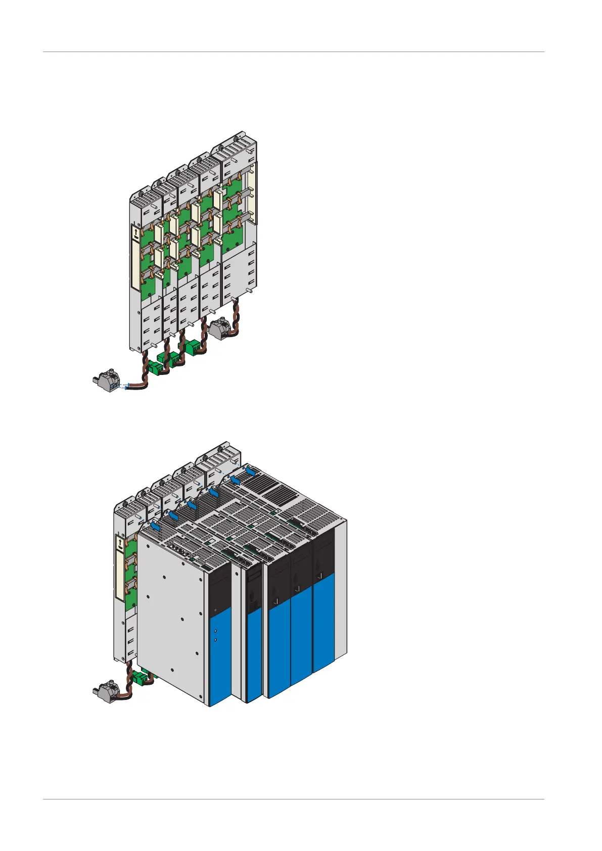
1. Remove terminal X22 from the appropriate terminal set. Connect the brown cable D+ of the
bottom of the Quick DC-Link module to D+ of terminal X22, and the black cable D- of the
Quick DC-Link module to D- of terminal X22. Note that the terminal is only connected at a
later point in time.
2. Place the drive controller or supply module on the bottom threaded bolt of the Quick DC-
Link module and properly align the device vertically with the bottom and top threaded bolt.