STOBER 7 | Project configuration
02/2019 | ID 442728.05
83
7.4.3 Sample calculation
Assume 20 motors, each with a nominal current of 2A and an operating time of 100% (full
load). The design calls for 10 SI6A062 double-axis controllers with a nominal output current of 2
× 5A.
1. Checking the self-capacitance of the drive controllers versus the charging capacity of
the supply module
The DC link capacitance in the group to be charged corresponds to the sum of the self-
capacitances of all drive controllers in the group: 10 × 0.27mF = 2.7 mF.
The maximum charging capacity of the PS6A24 supply module is 5mF.
This means one PS6A24 supply module is sufficient.
2. Determining current requirements and checking utilization
The nominal input current (DC) of a SI6A062 is 8.4A; the nominal output current is 5A per axis.
The motor's nominal current is 2A.
The current requirement for the specific application is 8.4A ÷ 5A × 2A = 3.36A per drive
controller. As a result, 10 drive controllers would need 33.6A.
The nominal input current of a PS6A24 supply module is 21A; the nominal input current of a
PS6A34 is 42A.
The PS6A24 supply module is not sufficient in terms of the current requirements. A PS6A34
supply module is needed.
3. Checking the length of the copper rails
The width of a SI6A062 drive controller is 45mm; the width of the PS6A34 supply module is
65mm.
The total length of the group corresponds to: 10 × 45mm + 65mm − 2 × 2.5mm = 510mm.
At 1500mm, the length of a standard copper rail is sufficient.
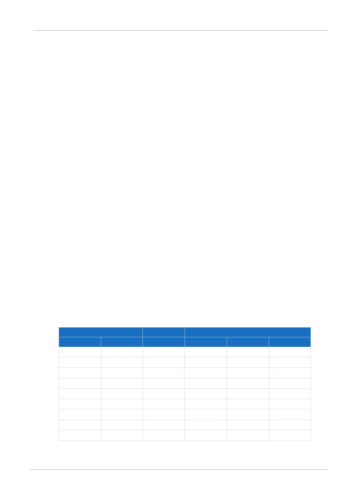
7.5 Order overview of the hardware components
Device Terminal set Quick DC-Link
Type ID No. ID No. Type ID No. Width [mm]
PS6A24 56650 138660 DL6B20 56656 45
PS6A34 56651 138661 DL6B21 56658 65
SI6A061 56645 138655 DL6B10 56655 45
SI6A062 56646 138656 DL6B10 56655 45
SI6A161 56647 138657 DL6B11 56656 65
SI6A162 56648 138658 DL6B11 56656 65
SI6A261 56649 138659 DL6B11 56656 65
SI6A262 56653 138662 DL6B12 56663 105
SI6A361 56654 138663 DL6B12 56663 105
Tab. 78: Overview of hardware components with ID No.