10 | Connection STOBER
110
02/2019 | ID 442728.05
10.4 Supply module
For detailed information about the terminals and correct connection of the supply module, refer
to the following chapters.
Information
For UL-compliant operation: The connections marked with PE are intended solely for the
functional grounding.
10.4.1 Overview
DC
-Link
max. 1000 V/
DC
High V
oltage
D+
D-
L2
L1
L3
PE
X100
2
4
3
5
3
4
2
1
6
6
8
X21
X22
X23
RB
RB
2
1
7
5
9
11
10
D
D
X10
1
1
X11
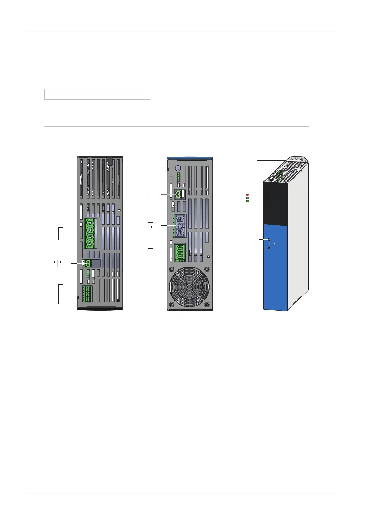
Fig.29: Connection overview using the example of the PS6A34
Top of the device Bottom of the device Front of the device
1 Ground bolt 5 Fan on/off switch 9 3 diagnostic LEDs
2 X10: 400V
AC
supply 6 X23: Braking resistor
temperature
monitoring
10 D+ DC link potential
measuring point
3 X11: 24V
DC
supply 7 X22: DC link
connection
11 D− DC link potential
measuring point
4 X100: Status output 8 X21: Braking resistor