STOBER 10 | Connection
02/2019 | ID 442728.05
135
10.5.18 X300: Brake 24V supply
X300 is used to supply the brake.
ATTENTION!
Device damage due to overload!
If the 24 V
DC
power supply is looped to multiple devices over the terminal, the terminal may be
damaged by a current that is too high.
▪ Make sure that the current over the terminal does not exceed the value 15A (UL: 10A).
Electrical data Single-axis controller Double-axis controller
U
1
+24V
DC
, +25%/−0%
I
1max
2.5A 2 × 2.5A
Tab. 134: Electrical data of the control unit brake control
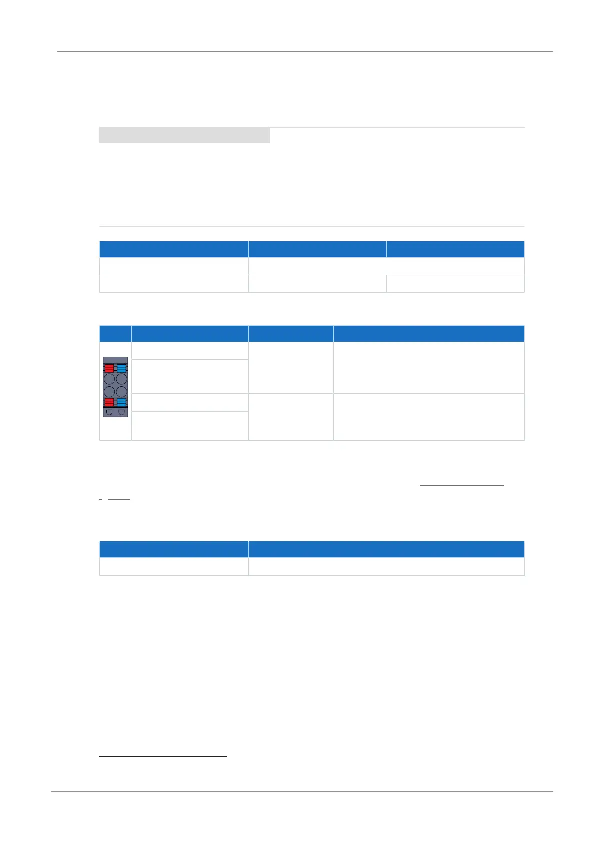
Pin Designation Function
1 | 3
2 | 4
1 + 24V
DC
supply for the brake; bridged in the
terminal; design in accordance with EN
60204: PELV, secondary grounded,
recommended fuse protection: max. 15AT
15
2
3 − Reference potential for power supply voltage
of the brake
4
Tab. 135: X300 connection description
For connecting wiring, observe the terminal specifications in the chapter BLDF 5.08 180 SN
[}234].
Cable requirements
Feature All sizes
Max. cable length 30m
Tab. 136: Cable length [m]
15
For UL-compliance, use of a 10A fuse (time delay) is required. Be sure that the fuse meets certification
requirements for DC voltage in accordance with UL 248.