10 | Connection STOBER
114
02/2019 | ID 442728.05
Wiring example
The examples in the chapter Wiring examples [}239] illustrate the basic connection based on a
DC link connection with DL6B Quick DC-Link.
10.4.6 X23: Temperature monitoring of braking resistor
Connect the temperature monitoring of the braking resistor to terminal X23. UL-compliant
operation: For project configuration of the braking resistor, observe the notes in the chapter UL-
compliant use [}19].
Pin Designation Function
1 | 2
1 1TP1 Temperature monitoring connection
2 1TP2
Tab. 93: X23 connection description
For connecting wiring, observe the terminal specifications in the chapter FKC 2,5 -ST-5,08
[}234].
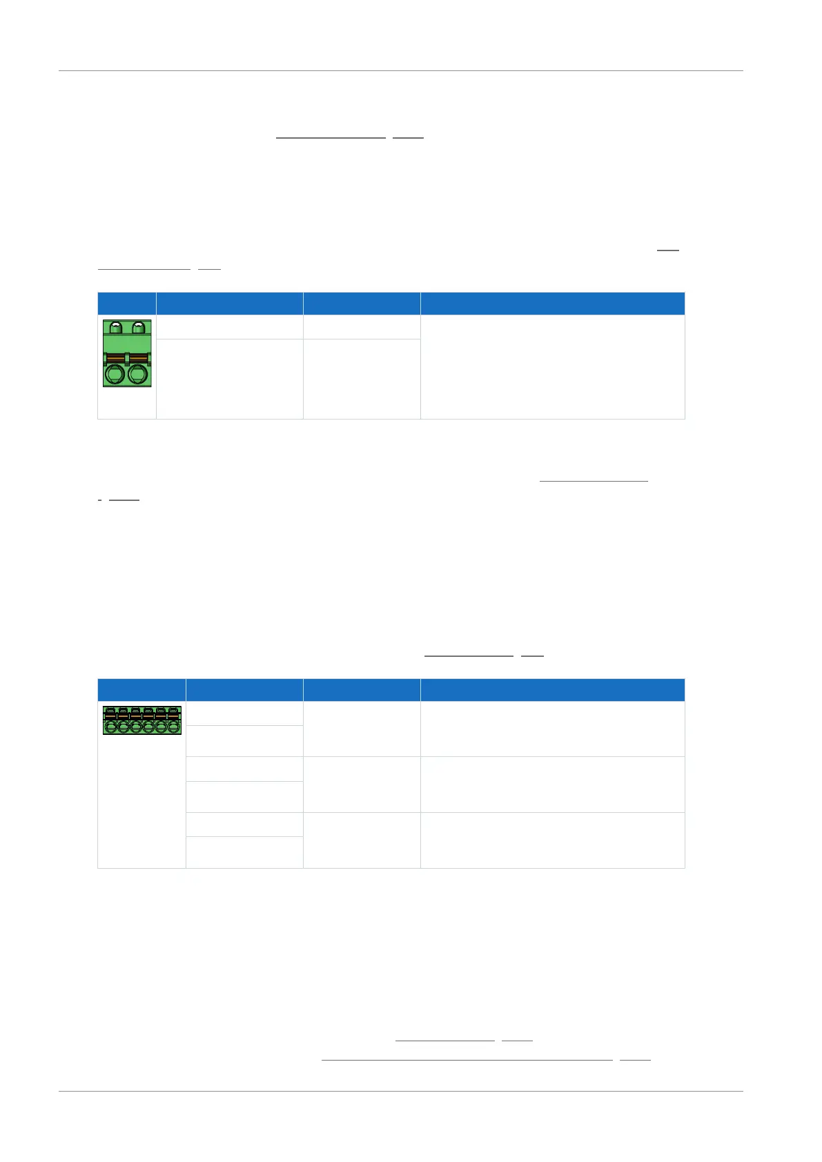
10.4.7 X100: Status output
The relay status output of terminal X100 in conjunction with the 3 diagnostic LEDs on the front
of the device provides information about the status of the supply module.
Technical data
Observe the technical data for X100; see the chapter Status output [}41].
Terminal Pin Designation Function
6|5|4|3|2|1
1 READY NO contact;
Operational status;
recommended fuse protection: max. 2AT
2
3 WARNING1 NO contact;
Warning status 1; Overload;
recommended fuse protection: max. 2AT
4
5 WARNING2 NO contact;
Warning status 2; grid phase failure;
recommended fuse protection: max. 2AT
6
Tab. 94: X100 connection description
Use a 2A fuse (time delay) upstream of the 3 relays for fuse protection.
For UL-compliant use, be sure that the fuse meets certification requirements for DC voltage in
accordance with UL 248. During UL-compliant operation, the PS6 supply module must be
removed from the power supply using the WARNING1 relay. An associated application is a
notification from the temperature switch when the braking resistor is overloaded.
You can find notes on diagnostics in the chapter Supply module [}169], and a wiring example
for correct connection in the chapter UL-compliant connection of the supply module [}241].