STOBER 10 | Connection
02/2019 | ID 442728.05
111
10.4.2 X10: 400V supply
Terminal X10 is used to connect the supply module to the supply grid.
Conductor cross-sections for the power connection
When selecting the conductor cross-section, note the line fuse, the maximum permitted
conductor cross-section of terminal X10, the routing method and the surrounding temperature.
UL-compliant operation
The chassis of the PS6A/SI6A units is to be bonded through the M6 grounding studs on the
PS6A units (4.0Nm, 35Lb.inch).
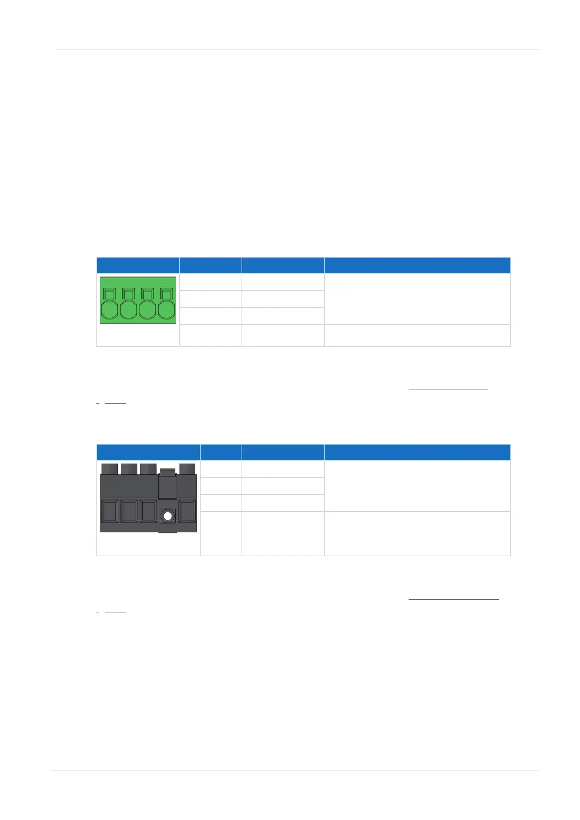
Size 2
Terminal Pin Designation Function
1 | 2 | 3 | 4
1 L1 Power supply
2 L2
3 L3
4 PE Grounding conductor
Tab. 85: X10 connection description – Size 2
For connecting wiring, observe the terminal specifications in the chapter SPC 16 -ST-10,16
[}237].
Size 3
Terminal Pin Designation Function
1 | 2 | 3 | 4
1 L1 Power supply
2 L2
3 L3
4 PE Grounding conductor
Tab. 86: X10 connection description – Size 3
For connecting wiring, observe the terminal specifications in the chapter BUZ 10.16IT 180 MF
[}238].