STOBER 6 | Technical data
02/2019 | ID 442728.05
41
6.2.1.5 Brake chopper
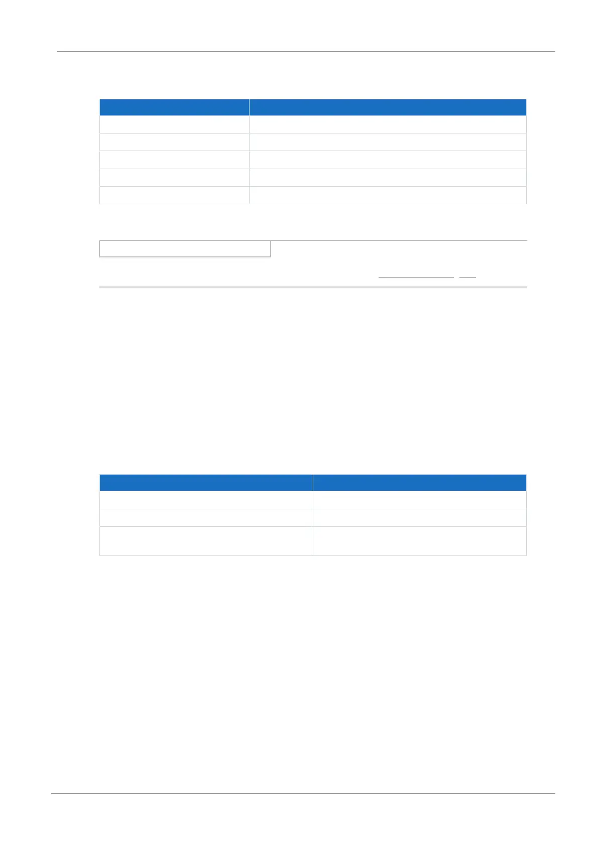
Electrical data All types
U
onCH
780–800 V
DC
U
offCH
740–760V
DC
R
2minRB
22Ω
P
maxRB
29.1kW
P
effRB
13.2kW
Tab. 19: Brake chopper electrical data
Information
Use braking resistors with thermal monitoring (see the chapter Braking resistor [}65]).
6.2.1.6 Fast discharge
Fast discharge is activated when no power supply is present for 20s and the DC link voltage
has reduced over this time. For active fast discharge, the DC link is discharged via the brake
chopper and the braking resistor. Fast discharge does not take place for constant or increasing
DC link voltage as this behavior indicates a second supply module in the DC link group. If the
temperature sensor of the braking resistor is active, the fast discharge also remains off.
6.2.1.7 Status output
The relay status output of terminal X100 in conjunction with the 3 diagnostic LEDs on the front
of the device provides information about the status of the supply module.
Electrical data Relay
U
2max
30V
DC
I
2max
2.0A
Expected service life Mechanical min. 100 000 000 switch.;
at 30V
DC
/2A (ohm. load): 100 000 switch.
Tab. 20: Electrical data