STOBER 10 | Connection
02/2019 | ID 442728.05
149
10.7.2.2 SSI encoders
Suitable encoder cables are described below.
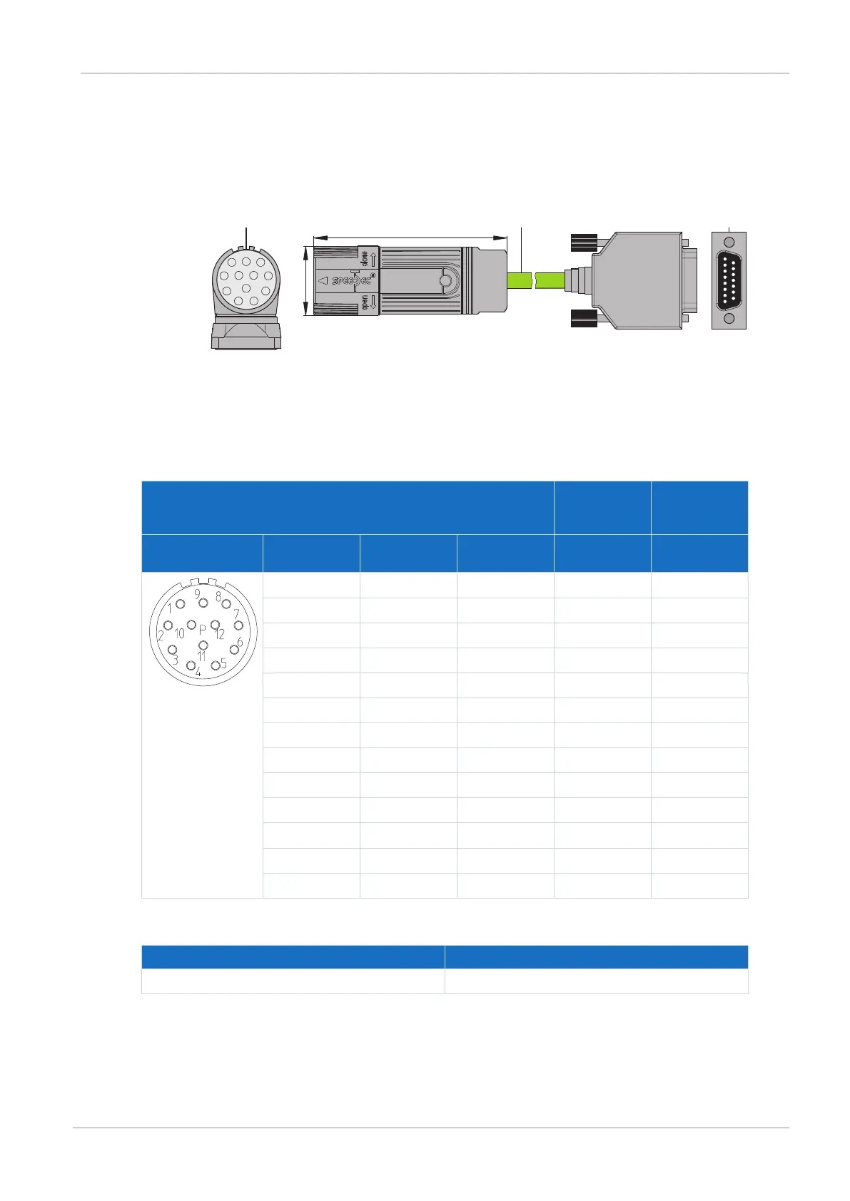
10.7.2.2.1 Connection description
1
3
1
P
9
2
4
5
8
7
6
10
11
12
con.23
32
1
15
x
y
1: Plug connectors
2: STOBER encoder cable
3: D-sub X4
Encoder cables – con.23 plug connector
Motor
(1)
Cable
(2)
Drive
controller
(3)
Connection
diagram
Pin Designation Core color Core color Pin
X4
1 Clock+ VT YE 8
2 Sense U
2
BNGN PK 12
3 — — — —
4 — — — —
5 Data− PK BN 13
6 Data+ GY WH 5
7 — — — —
8 Clock− YE GN 15
9 — — — —
10 GND WHGN BU 2
11 — — — —
12 U
2
BNGN RD 4
Housing Shield — — —
Tab. 151: con.23 encoder cable pin assignment, SSI
Length x [mm] Diameter y [mm]
58 26
Tab. 152: con.23 dimensions