English
1-46 2131-009-005 REV A www.stryker.com
Return To Table of Contents
Footboard Operation Guide
Maintenance
Close
Error Codes
Signal Values
Boards
Buttons Pressed
Bed
Informations
Input
States
Nurse Control
Close
Signal Values (All)
Sensor Values
Temp
24 Vdc
Battery Voltage
VBus
Brake Pot
Charger Amp
31.2 C
26.2 V
25.1 V
24.7 V
70
0.00 A
Load cells values
Load cells
Angle dep. trend
Angle indep. trend
Angle dep. rev. trend
Angle indep. rev. trend
Bed exit
Bed height
Foot end Height
x = 54, y = 22
711
869
1
45.9 lb
34062
-27540
32095
-25573
2
57.5 lb
-27139
28195
-25262
26318
3
76.3 lb
-18274
24436
-22896
29058
4
100.0lb
24793
-24573
29827
-29607
Tilt Values
Head
Gatch
Foot
Base
Hilo foot
Trend
Angle
-13.6
11.6
-10.9
0.0
76.0
11.6
Raw
3980
5211
4334
5246
5200
5411
Zero
5029
5439
5071
5247
4627
5172
Gain
813962
-880336
796641
800000
791613
838363
Close
Error Codes
Current error
ADC invalid values
Battery absent
Battery bad capacity
Cmd without safe from nurse (SRR)
GPIO failure init
Load cell 1 overrange
Motor gatch overheat
Motor brake overload
Motor HL foot overheat
Motor zoom overheat
Safe without cmd from B1
Tilt hilo foot over range
Tilt gatch over range
Brake bad calib.
Brake unable to elec.
ADC invalid values
Battery absent
Battery bad capacity
Cmd without safe from nurse (SRR)
GPIO failure init
Load cell 1 overrange
Motor gatch overheat
Motor zoom overheat
Safe without cmd from B1
Tilt hilo foot over range
Error log
Clear log
Back
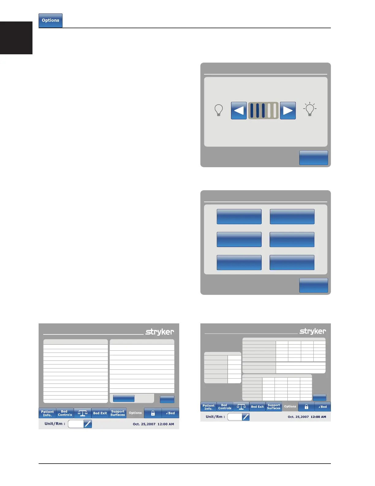
Figure 8.10
Figure 8.11
Figure 8.12
Figure 8.13
MAIN MENU: OPTIONS (CONTINUED)
Nurse Control Backlight Button
When the “Nurse Control Backlight” button is
pressed on the Options screen, Figure 8.10 will be
displayed. The backlighting interface allows the
user to set the intensity of the indicators (LED) and
of the touch screen.
Press the arrows to increase or decrease the
intensity. When completed, press the “Close”
button.
Maintenance Button
When the “Maintenance” button is pressed on the
Options screen, Figure 8.11 will be displayed.
When the “Error Codes” button is pressed, Figure
8.12 will be displayed. The Error codes display
provides information on component status.
When the “Signal Values” button is pressed, Figure
8.13 will be displayed. The Signal Values display
provides information on sensor status.
Note
Refer to the Maintenance Manual for further details
on Buttons Pressed, Boards and Bed Information.