English
www.stryker.com 2131-009-005 REV A 1-75
Return To Table of Contents
Traction Sleeve - FA64215 through FA64219
The Optional Traction Sleeve enables the installation of traction equipment. There are five different size configurations
available as shown below. The installation procedures below apply to all configurations listed.
NOTE: The foot end section of the mattress is stopped when a traction socket or I.V. pole is inserted.
• Traction Sleeve Set - 4” x 1/2” FA64215
• Traction Sleeve 4” x 3/4” FA64216
• Traction Sleeve 8” x 1/2” FA64217
• Traction Sleeve 8” x 3/4” FA64218
• Traction Sleeve 6-1/2” x 3/4” FA64219
INSTALLATION
Required Tool:
• 7/16” Combination Wrench
Procedure
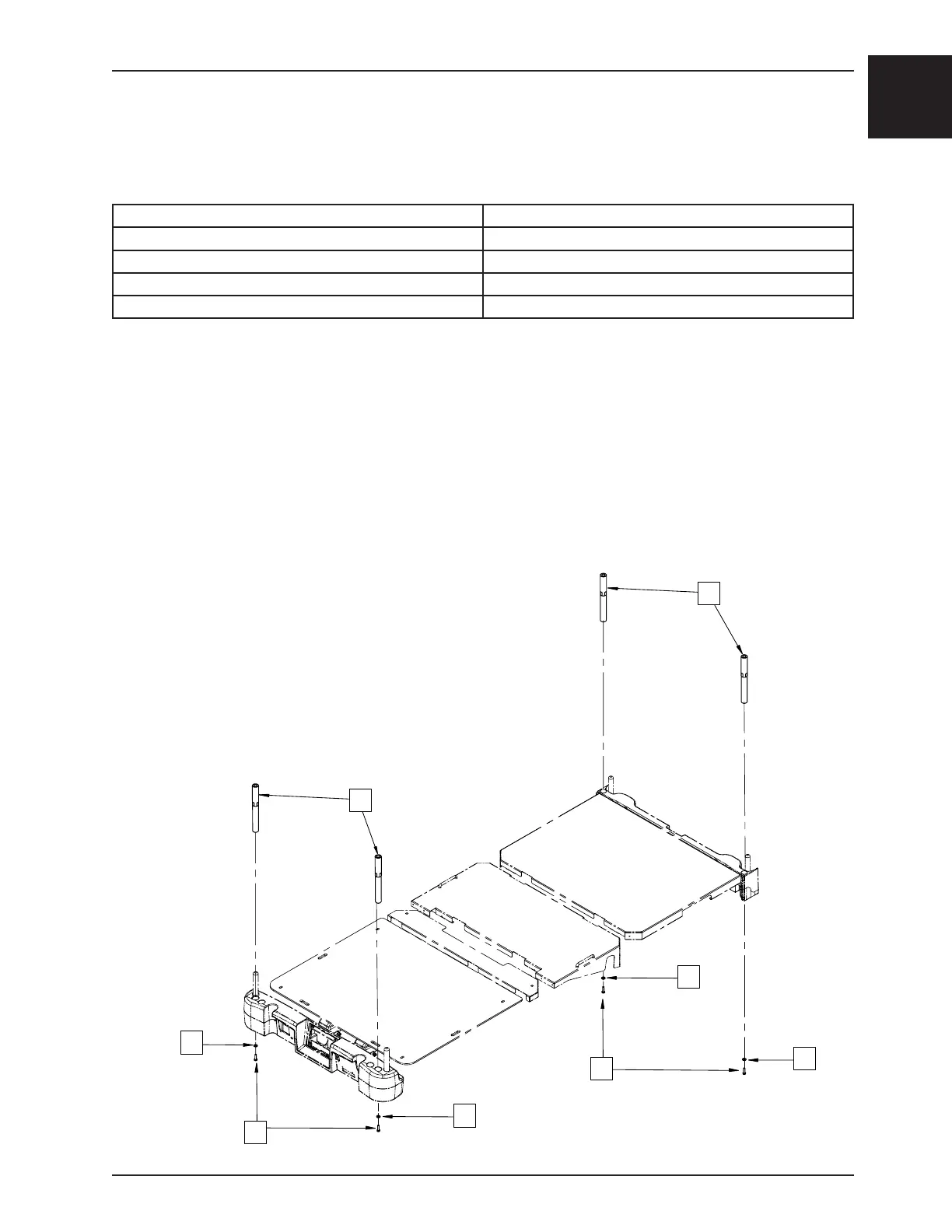
1. Install the four traction sleeves (A) in the corresponding holes located at the four corners of the bed.
2. Secure them using the washers (B) and bolts (C) provided.
Note: The bolt used at step 2 is coated with “Scotch Grip”. This type of bolt must be replaced by a new
identical bolt if it is removed following a first installation.
A
B
A
C
C
B
B
B