SWDM40 OPERATION & MAINTENANCE MANUAL
FIG.8-3-1
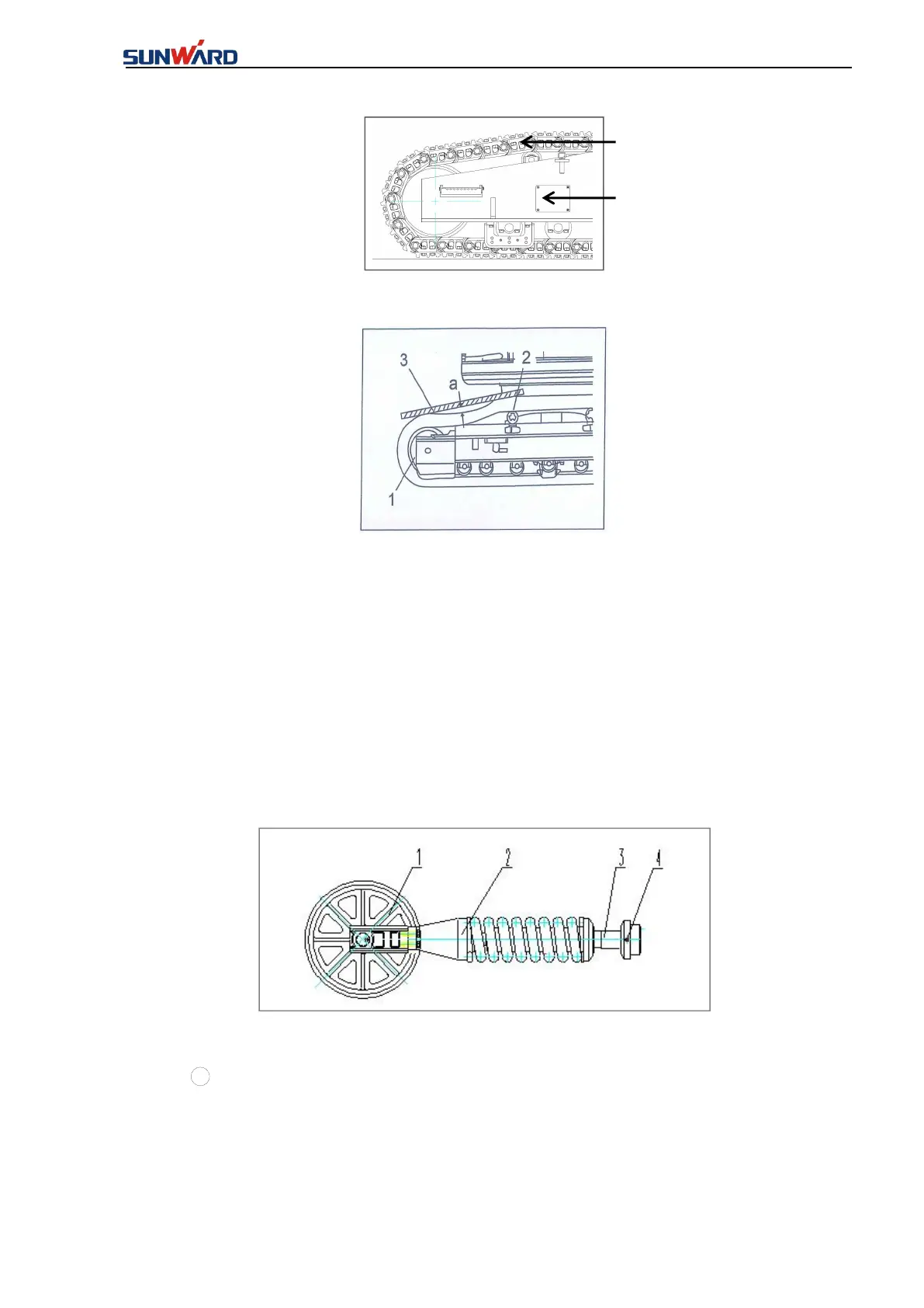
FIG. 8-3-2
(1)Idler (2)Carrier roller (3)Ruler (a)Track sag
1. Operate the machine according to the direction of idler, place the drilling rig on firm level
ground and place the track pin shaft (1) right on the carrier roller (2).
2. Put a ruler (3) on the track, and it should be long enough to measure from idler (1) to carrier
roller (2).
3. Measure the maximum sag for track, which is measured from the lowest point to the bottom
of the ruler and adjust the track correctly. The track sag “a” is about 20mm to 35mm.
FIG. 8-3-3
1 Idler
②
Cushion spring
③
Tension cylinder
④
Grease nozzle
Tension device includes tension cylinder, cushion spring, idler and grease cup. If the track is too
tight or loose, please refer to below procedures “track tension tightening or loosening” to adjust.