CHAPTER TWO - INSTALLATION
16
SG-System I Operating Manual
2
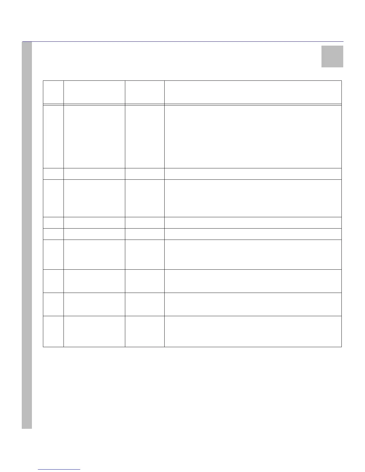
5 LCD Display 40x2 character LCD display.
Top line displays current Operating Mode.
Bottom line displays Trouble or received messages in Manual mode.
Alarm: If an alarm is present while the system is in Manual mode, the LCD
backlight will change to Red - overriding the programmed colour - and the
ACK button will flash. In addition, a buzzer will sound with each flash of the
ACK button.
Alarms received but not yet displayed are identified by a solid arrow symbol on
the far right edge of the LCD.
6 DOWN Interface Button Scrolls down through menu options.
7 ACK Interface Button/
LED
FLASHING
OFF
Indicates unit is in Manual Mode and waiting for acknowledgement.
There are no alarm events requiring acknowledgement.
The ACK button is used to acknowledge an alarm event in Manual Mode. It
cannot acknowledge all alarms with one press, but must be pressed for each
individual alarm.
8 UP Interface Button Scrolls up through menu options.
9 ENTER Interface Button Selects a menu option.
10 AUTOMATION Port
(COM1)
DB9 Sends automation messages to central station computer (e.g. heartbeat if no
activity).
NOTE: Maximum cable length is 1.8m (6ft). Longer cables may
impair performance.
11 PARALLEL PRINTER
Port
DB25
(Female)
Sends events to local printer (DB25 Female).
NOTE: Maximum cable length is 1.8m (6ft). Longer cables may
impair performance.
12 SERIAL PRINTER Port
(COM2)
DB9 RS232 Serial Printer Port. Sends events to local printer.
NOTE: Maximum cable length is 1.8m (6ft). Longer cables may
impair performance.
13 Telephone Line Input 2 x RJ-11 For connection with PSTN (alarm reporting connections using digital diallers-
DACT).
Pins 3 and 4 are line-in; pins 2 and 5 are backup channel line-in or two-way
audio connection.
Table 3: SG-System I Front and Rear Panel Descriptions
Item
no.
Indicator/ Control/
Connector
State/Pin
Description