CHAPTER TWO - INSTALLATION
17
SG-System I Operating Manual
2
For ULC installations Canada, the equipment shall be rack-mounted and powered by a permanently wired supply in accor-
dance with C22.1, Canadian Electrical Code, Part 1, Safety Standard for Electrical Installations, section 32. Please refer to on
page 19. This equipment is intended to utilize the building emergency AC supply system for their standby supply (e.g. UPS,
batteries in conjunction with engine-driven generators).
NOTE: The LED indicators and the LCD can be tested for integrity by accessing the following in the main programming
menu: item 3 - System Functions > item 5 - Visual Indicators Test.
NOTE: For equipment used at Signal Receiving Centres and intended to facilitate IP communication (hubs, routers, NID,
DSL/cable modems) 24hr backup power is required.
NOTE: When using Private, Corporate, and high-speed data networks, network access and domain access policies will be
set to restrict unauthorised network access and ‘spoofing’ or ‘denial of service’ attacks. Select an ISP that provides redun-
dant servers/systems, backup power, routers with firewalls enabled and methods to identify and protect against these types
of attacks (‘i.e. ‘spoofing’, ‘dos’).
14 I/O Port ( Use AWG 18-
22 wire)
1 Input
2 ~
3 Input
4 Input
5 ~
6 Input
7 Output R1*
8 R1
9 Output R2
10 R2
11 Output R 3
12 R3
13 ~
UPS AC Failure (toggles from ground to open on failure)
Common (ground)
UPS DC Failure (toggles from ground to open on failure)
Remote ACK button - identical functionality to ACK button on LCD
Common (ground)
Future Use
Follow Buzzer: relay contact closes following Buzzer output activations (syn-
chronized)
Relay Common
Trouble Output: relay contact closes when the Trouble LED activates
Relay Common
Network Status: relay contact closes when the Network Status icon appears on
the LCD
Relay Common
Earth (ground)
NOTE: Maximum cable length is 1.8m (6ft). Longer cables may
impair performance. The use of shielded cable is recommended.
NOTE: Relays are rated for 12Vdc 100ma.
NOTE: Inputs are rated for 20ma open collector.
*Rx is the relay number; as a rule, these outputs are open connections
15 USB Port USB Type B USB Type B. The USB port on SG System I is used to connect with a Windows
host running the SG-Systems Console Software. Other operating systems are
not supported.
NOTE: Maximum cable length is 1.8m (6ft). Longer cables may
impair performance.
16 LAN Interface Port CAT-5 This interface connects to the local network. Also, it is through this interface
that a connection is made to the console software and the automation software.
NOTE: Maximum cable length is 100m (328ft). Longer cables may
impair performance.
17 Mains Supply Connector 120/240VAC /0.7A/ 50-60Hz
Connection to Interruptible Power Supply (UPS recommended) with minimum
24 hr. standby capability required.
Refer to Set Up and Testing on page 18.
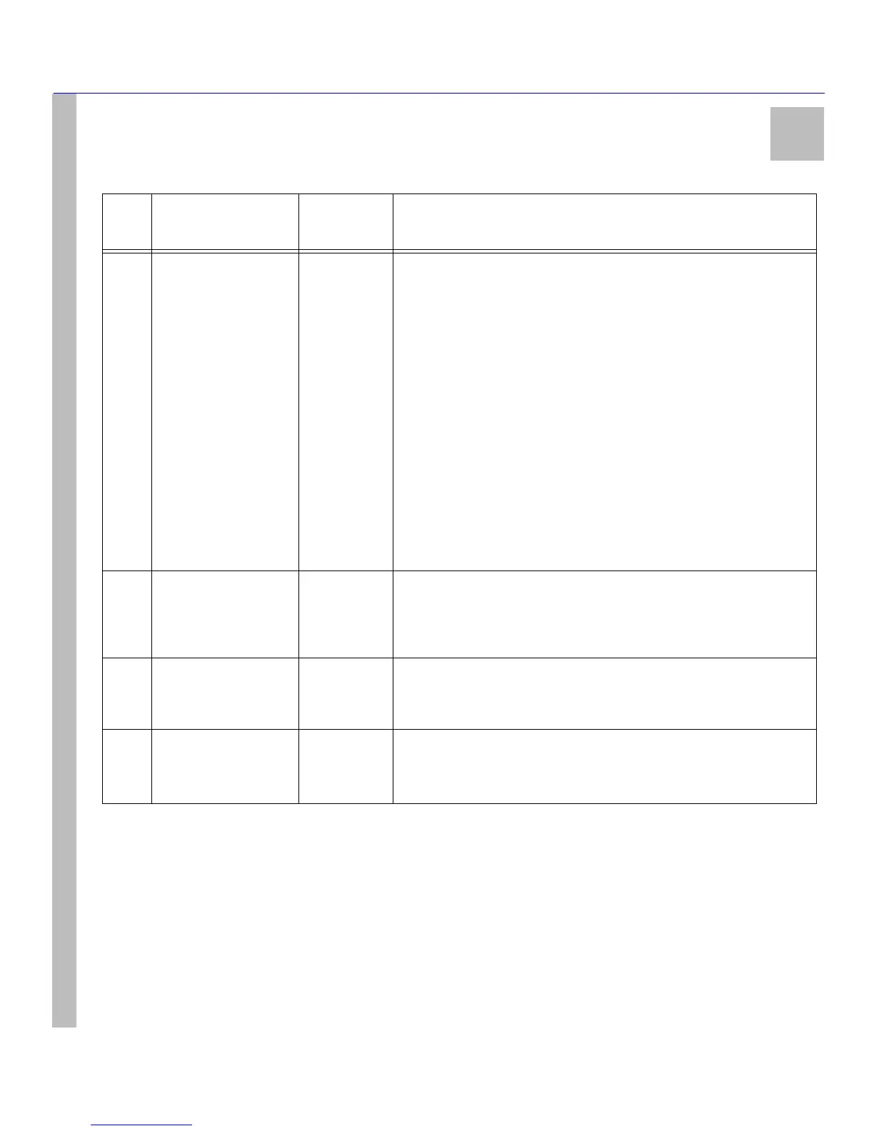
Table 3: SG-System I Front and Rear Panel Descriptions
Item
no.
Indicator/ Control/
Connector
State/Pin
Description