Page 3.3
3.1.4. CARDIO RECEIVER
This is the Board that manages the signal sent by the Telemetric Transmitter (Heart Rate Band),
used by the user during training sessions. The Receiver Board receives a power supply of +5Vdc
from the Display Board.
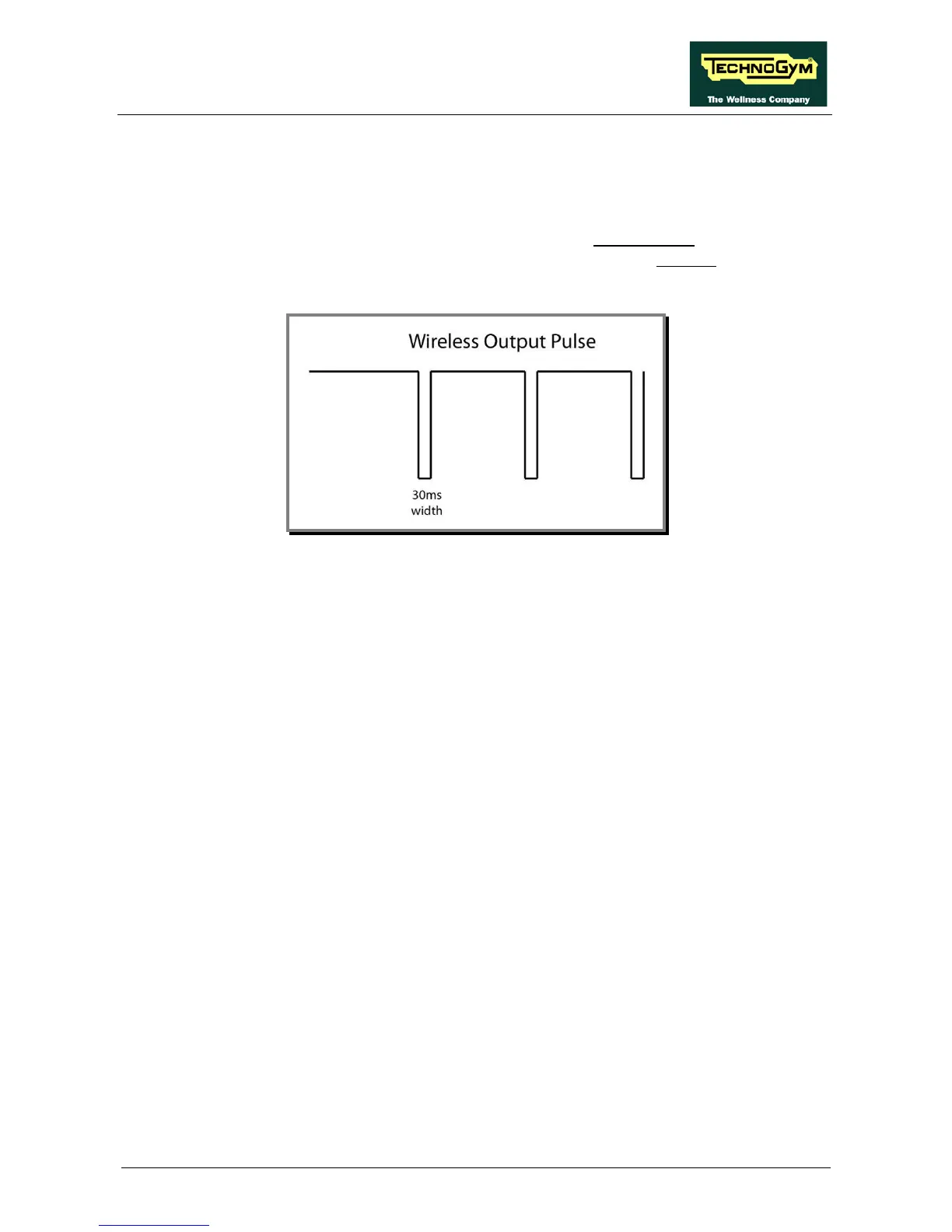
The Receiver Board communicates with the Display Board using negative logic procedures. When
it is in stand-by, the signal has a +5Vdc value and with every heart beat it picks up, it generates an
impulse of +0Vdc with an amplitude of 30msec.
3.1.5. BRAKE BOARD
Every Brake Board is divided up into:
1. Power supply section which generates the low voltages used by the equipment: +5Vdc (used
only by high kits of the LED type) and +12Vdc (used by all types of high kits). Depending on
the equipment version, these voltage levels are originally generated from mains voltage (both
110Vac and 220Vac) or by a battery-generator.
2. Section that communicates with the Display Board (high kit) on the RS-485 serial line in
order to manage:
the signals for controlling the resistance which needs to be supplied to the
Electromagnetic Brake;
the error messages relating to the Electromagnetic Brake;
the signals modifying the board's configuration parameters;
the signals displaying the memory of errors detected by the board;
the signals relating to use of the equipment (RPM, WATT, distance etc...)
3. Section that generates the current for the winding of the Electromagnetic Brake: when the
current varies, the resistance supplied to the Brake itself also varies proportionately. The
excitation current supplied to the Brake varies according to the user power/torque requested
by the display and the number of revolutions detected by the speed sensor (RPM).