CROSS FORMA: Service & Maintenance Manual - rev. 2.1
Page 3.8
3.2.3. THE SIGNALS INVOLVED
During control, the following signals may occur:
• RS-485 Signal
It is a digital signal between the Brake Board and Display Board. We have no possibility of
monitoring its state.
• Excitation current
This is the current generated by the Brake Board (pin 1-2 of the CN2 connector) and used to
power the brake winding. The power supplied is a function of the adjustment algorithm.
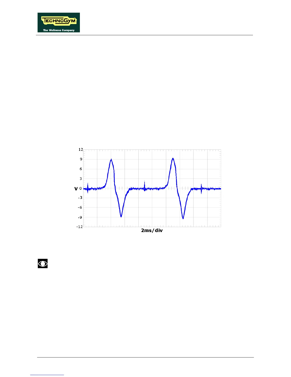
• Impulses from the speed sensor (speed sensor or generator, according to the type of
equipment)
This is the signal produced by the speed sensor and it normally appears as in the following
illustration:
Figure 3.2-1
This enters the Brake Board (pin 3-4 on CN2 connector) and here it is used to determine the
speed value (RPM) which is sent to the Display Board via the RS-485 serial cable.
This signal can also be measured qualitatively using a multimeter. When the equipment
is stationary, the voltage measured on the sensor is 0Vdc, whereas it varies by several
hundred mV and more during pedalling: the higher the speed, the greater the value
measured.