CROSS FORMA: Service & Maintenance Manual - rev. 2.1
Page 3.6
3.2. BRAKE CONTROL
3.2.1. THE MECHANICS
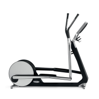
The movement of the pedals sets the primary shaft into rotation.
The primary shaft is attached to the secondary shaft and then to the brake, via a belt. The speed
sensor, built into the frame, detects the heads of the screws that fix the disk to the flywheel and
generates a signal representing the speed.
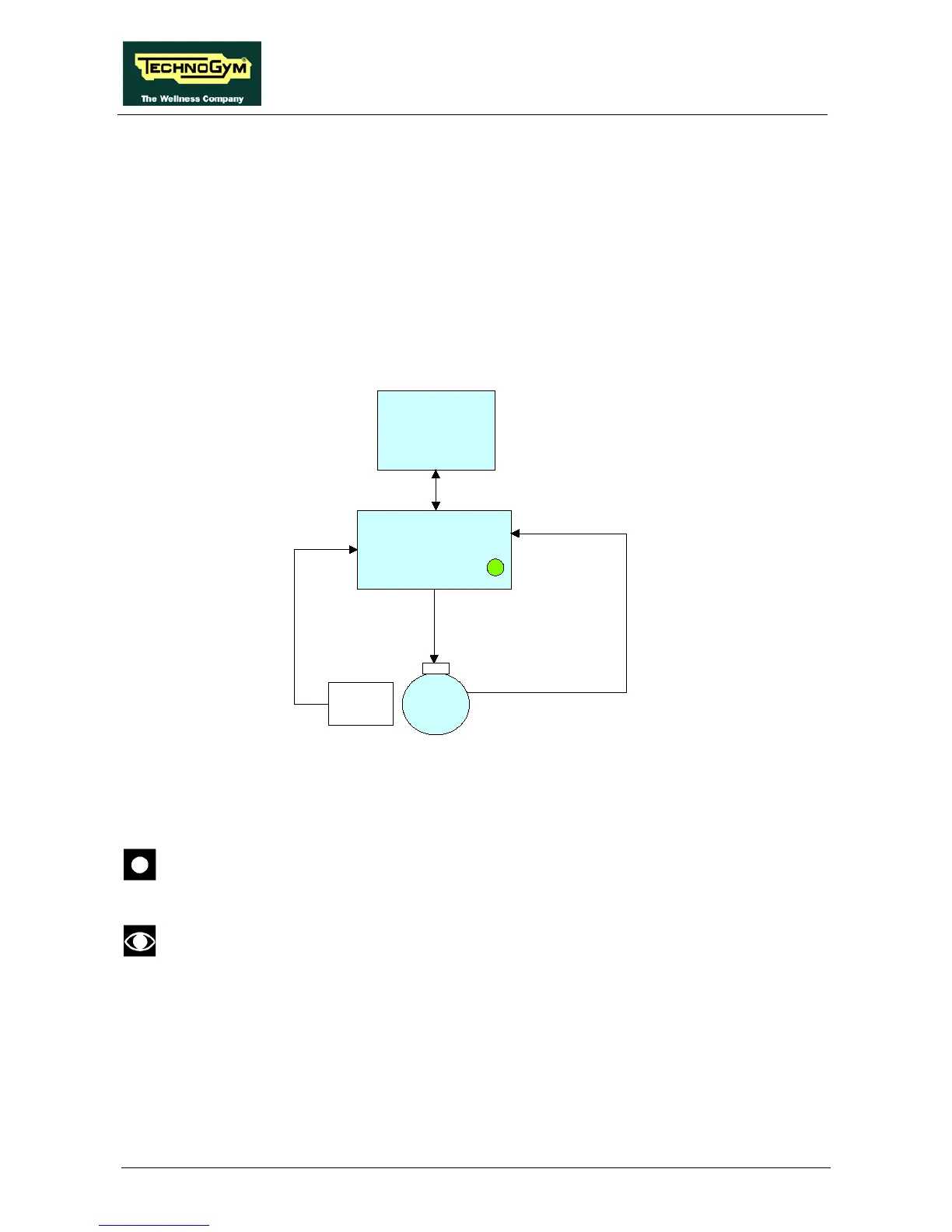
3.2.2. CONTROL
The control diagram is as follows:
In order to set up a specific exercise difficulty, the Brake Board communicates with the DISPLAY
Board via the RS-485 serial cable indicating speed value of the exercise in revs per minute (RPM).
On the basis of the commands received from the Display Board, the Brake Board sends an
excitation current to the winding on the brake which will generate an electromagnetic field.
WARNING: When the Brake Board receives the signal to start the exercise from the
Display Board, the green LED comes on and current is supplied to the electromagnetic
brake; provided that RPM ≠ 0.
When the brake Board receives the signal to generate resistance, the green LED comes
on.
Due to the electromagnetic field produced by the Current sent from the Brake Board to the winding,
and by the rotation of the disk, eddy currents will be induced on the disk itself which will generate a
force that will tend to slow down its movement. This will then generate Resistance on the pedals.