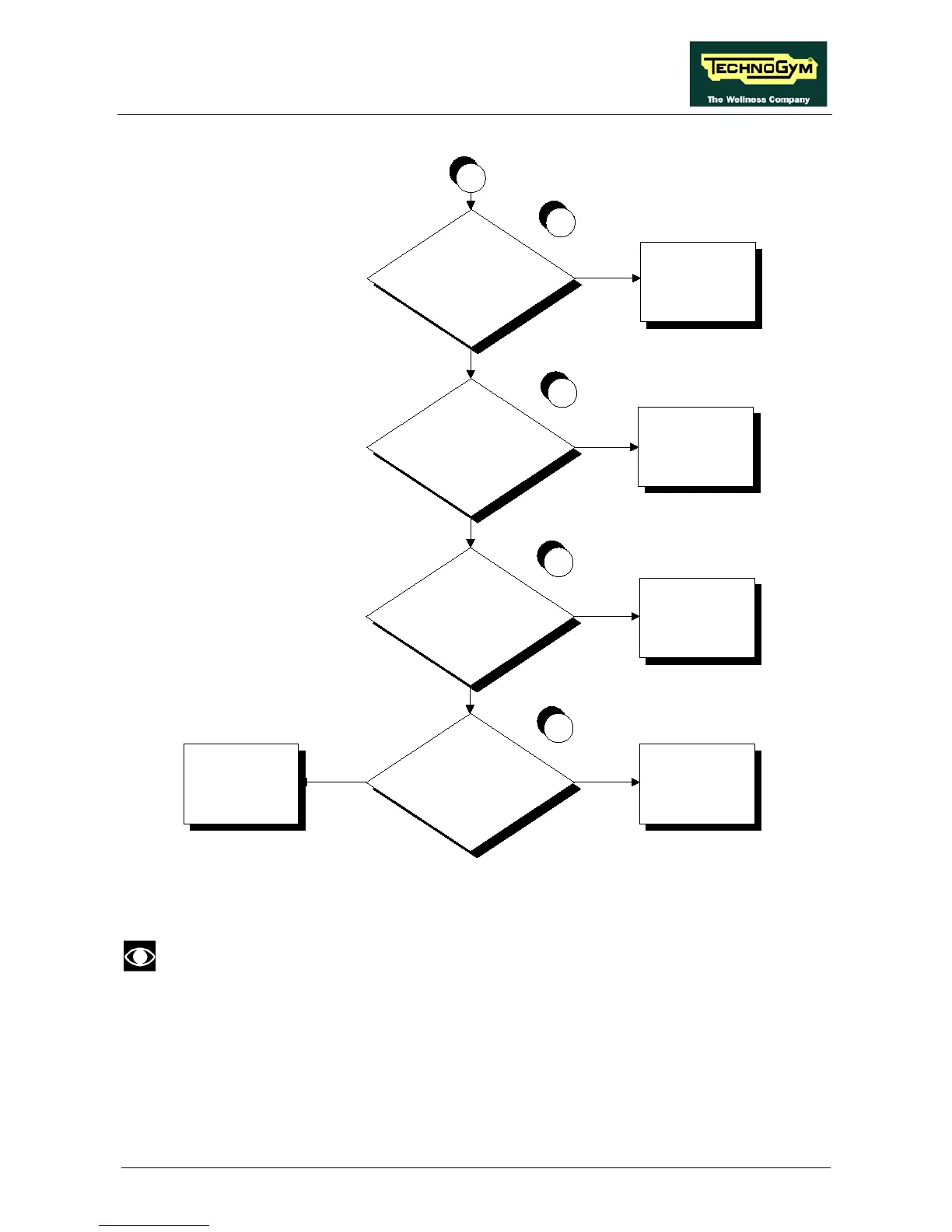
A
Are the DC v oltages at the
output of the brake board
correct?
3
NO
Are the DC v oltages on the
patch conn. 1 correct?
Replace cable
CF-01
NO
YES
4
Replace the brake
board
Does the mains voltage
reach the input to the
brake board?
NO
YES
2
Replace cable
CF-00
Are the DC v oltages at the
input to the display board
correct?
Replace the display
board
Replace cable
CF-02
NO
YES
YES
5
Follow the procedure step by step to correctly diagnose the problem. Take particular care with the
checks highlighted by circled numbers, which are described in detail below:
To speed up the troubleshooting procedure, check the state of the power indicator LEDs
on the various circuit boards.
(1) Slightly lift up the fastons on the machine power entry module. Place the tester probes across
the live and neutral pins on the same connector. The measured value should be approximately
220 VAC or 110 VAC depending on the mains voltage.
(2) As for step (1) but across pins 3 and 1 of connector CN4 on the Brake board.