C
LEAR
P
ATH
-EC
U
SER
M
ANUAL REV
1.11
15
T
EST
DC
P
OWER
P
OLARITY
IMPORTANT: Reversing DC Bus Power polarity will permanently
damage your ClearPath motor.
Important Notes
x If using Teknic manufactured cables, you can safely skip this
test.
x Do not force or jam DMM probes into the connector.
Use smaller probe tips or find a safe alternative way to verify
that polarity is correct.
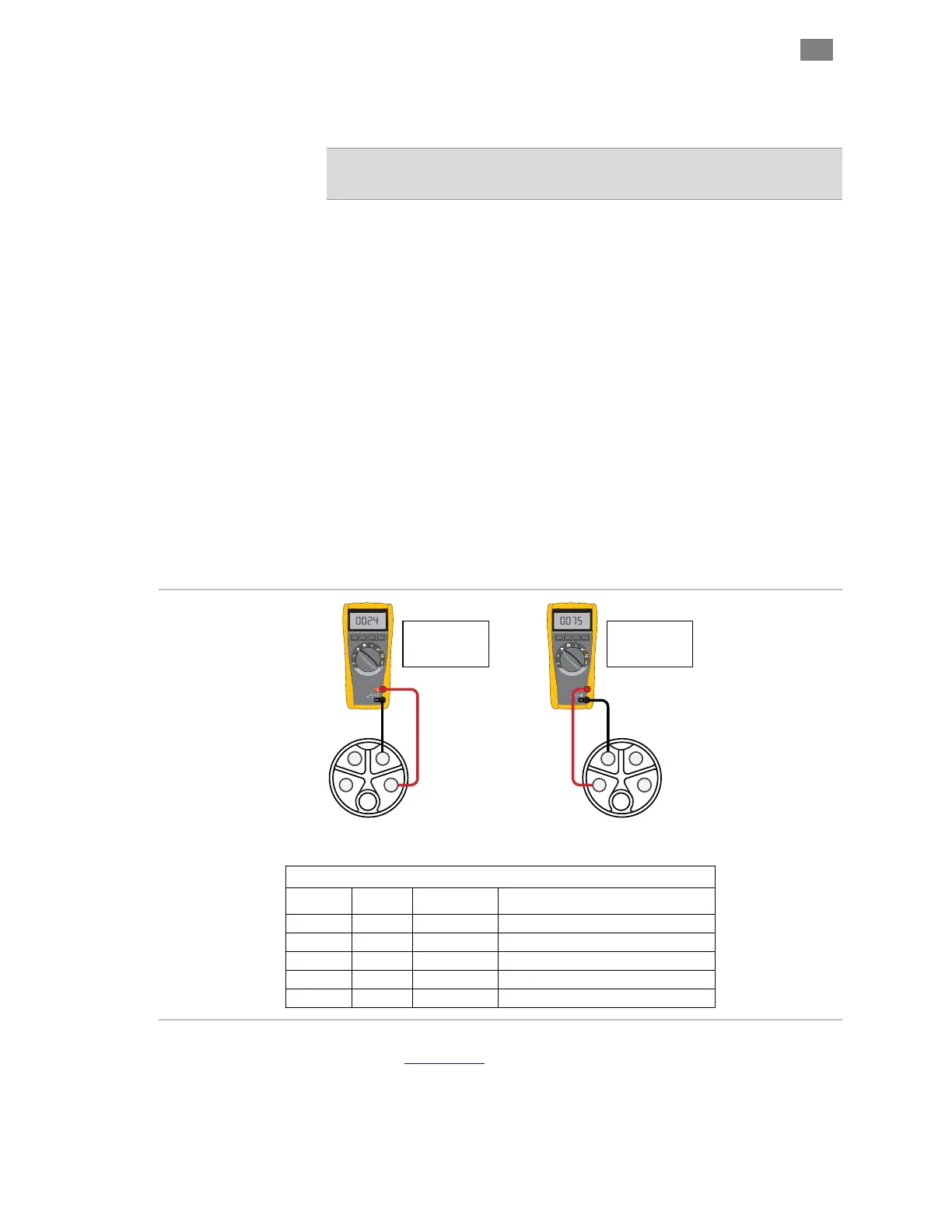
1. Start with the 5-position power connector disconnected from your
ClearPath-EC motor and the AC unplugged.
2. Power up your DC Bus Motor Power Supply.
3. Measure DC Bus Motor Power Supply voltage and
polarity. With a multimeter, measure the DC voltage from Bus
Motor Power+ (positive) to Bus Motor Power- (negative).
4. Power-up your logic power supply, if applicable.
5. Measure Logic Supply voltage and polarity. With a DMM,
carefully measure the Logic Supply voltage between Logic Power+
and Logic Power.
Terminal Assignment Table
Position
Wire Size
Color
Signal
1
16 AWG
Red
Bus Motor Power +
2
16 AWG
Black
Bus Motor Power -
3
22 AWG
Blue
Logic Power -
4
22 AWG
Orange
Logic Power +
5
N.C. N.C.
-
1
23
4
5
1
23
4
5
Logic Power
12-75VDC
VDC
VDC
+ +
_ _
DC Bus
Motor Power
24-75VDC
Testing Logic Power Polarity
(viewed looking into power cable)
Testing Logic Power Polarity
(viewed looking into power cable)
Check power polarity with a DMM
Note: See Appendix C for links to cable drawings and pinouts.
T
EKNIC
,
I
NC
. T
EL
.
(585)
784-7454