C
LEAR
P
ATH
-EC
U
SER
M
ANUAL REV
1.11
27
I
NPUTS AND
O
UTPUTS
O
VERVIEW
:
C
LEAR
P
ATH
-EC
I/O
C
IRCUITS
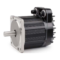
ClearPath-EC motors include two fully-protected, fully-isolated, high-
speed digital I/O circuits for connecting sensors, actuators, and logic level
devices. These circuits are referred to as I/O-A and I/O-B in this
document.
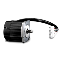
The I/O signals are routed from the M12 Adapter to the motor by means
of a controller cable. The I/O-A and I/O-B circuits are accessible via a
Molex MiniFit Jr. 8-pin connector on the M12 Adapter.
x Each of the I/O circuits can be configured as either an input or
an output.
x I/O-B only (i.e. not I/O-A) can be configured (as an output) to
control a typical 24VDC, power-off motor brake.
4
8
3
7
1
5
2
6
wired
as
Input A
wired
as
Output A
I/O-A2
I/O-A1
I/O-B2
I/O-B1
6
11
M12 Adapter
(Molex-8)
Motor Pin # (M12-12A)
A1
A2
48V
clamp
diode
48V
clamp
diode
wired
as
Input B
wired
as
Output B
10
12
B1
B2
Brake P
Brake M
Jumper
24V Ret.
Brake Control Circuitry
see Appendix G
for complete schematics
Note: Power polarity
differs based on whether
I/O circuits are used as
Inputs or Outputs.
ClearPath Motor internal
5
1
6
2
7
3
8
4
I/O-B2
(24VDC)
I/O-B1
I/O-A2
I/O-A1
Jumper
24V Ret.
Brake M
Brake P
The polarity of I/O circuit power depends on whether the circuit is used as
an input or as an output. For example, in the figure above, if I/O-A is used
as an input, the user would apply power such that pin 4 is (+) and pin 8 is
(-). Conversely, if I/O-A is used as an output the applied power polarity
would be pin 8 (+) and pin 4 (-). The I/O wiring examples later in this
section will show this more clearly.
This configuration allows the input and output circuits to be robustly
protected while minimizing interference from parasitic circuit elements.
Current is limited in both input and output configurations for protection
and to eliminate the need for external resistors. Both the input and output
circuits operate from 5V logic levels up to 24V industrial circuit levels.
In addition, the I/O circuits are optically isolated from the internal
processor and from each other. This allows these A and B circuits to sink
T
EKNIC
,
I
NC
. T
EL
.
(585)
784-7454