Transmitting Waveforms
Plotting or Printing a
W aveform
©
I AU XILIARY C O NNECTO R I
RELAY N.O.
+4.2 VDC
..
| j
----
Ht
" i I I r
RELAY COMM
SIG GND
EXTCLK
RELAY N.C.
i t t i t t - '
----
j y L_ cuiei
SHfELD GND
ADDR
L
PARAMETERS
5~m
EOI“*
J h2
f
....
•• .1
0 1
-1 8
LF OR EQI
r LON
TON
-AUX1
“ AUX2
©
f CAUTION T
<25V p k AND < 100mA ABS, MAX
. APPLIED TO ANY CONNECTOR ,
IEEE STD 488 PORT
S H I, AH1, T5, L3, S R I, RL2, PRO
DC1, DTO, CO, E2
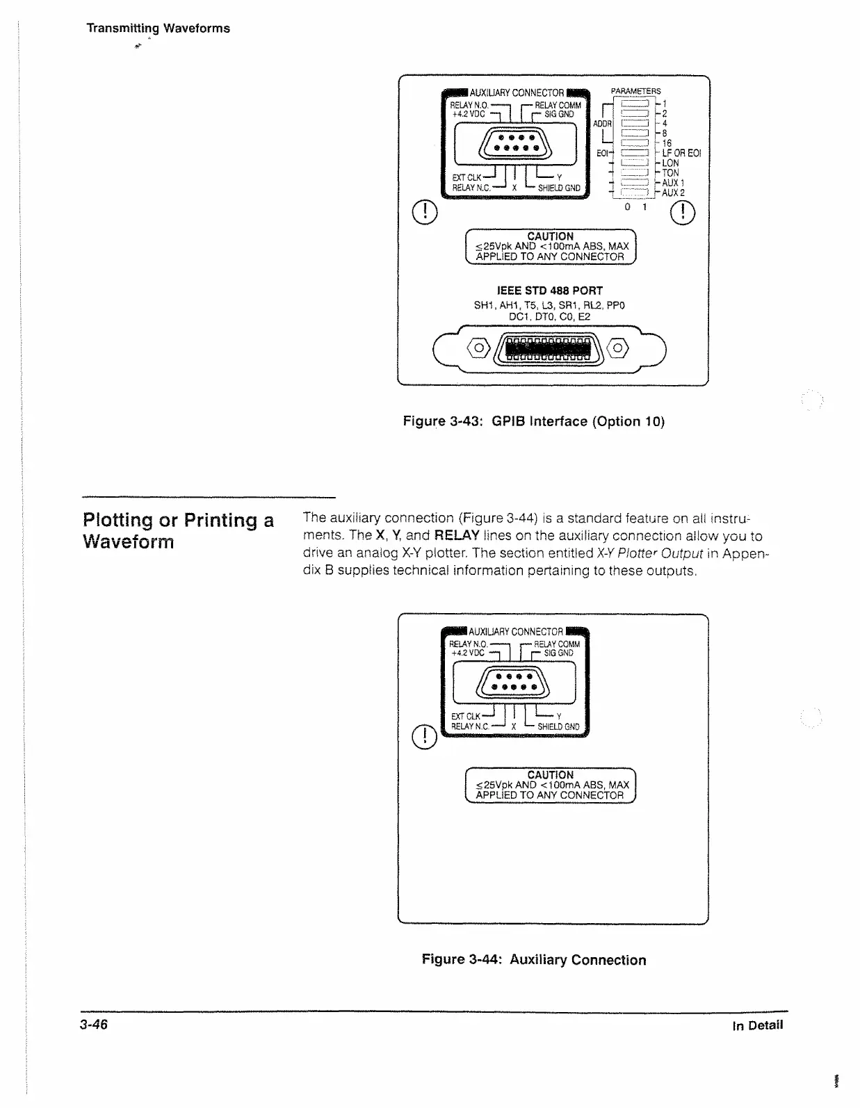
Figure 3-43: GPIB Interface (Option 10)
The auxiliary connection {Figure 3-44) is a standard feature on all instru
ments. The X, Y, and RELAY lines on the auxiliary connection allow you to
drive an analog X-Y plotter. The section entitled X-Y Plotter Output in Appen
dix B supplies technical information pertaining to these outputs.
mm
AUXILIARY CO N NECTO R H I
RELAY N.O.
------
1 r * “ RELAY COMM
+4.2 VDC -“ i r— SIG GNO
SHIELD GNO
CAUTION
<:25Vpk A N D < 1 00m A ABS, MAX
APPLIED TO ANY CONNECTOR
Figure 3-44: Auxiliary Connection
3-46
In Detail

 Loading...


