Front Panel
*r
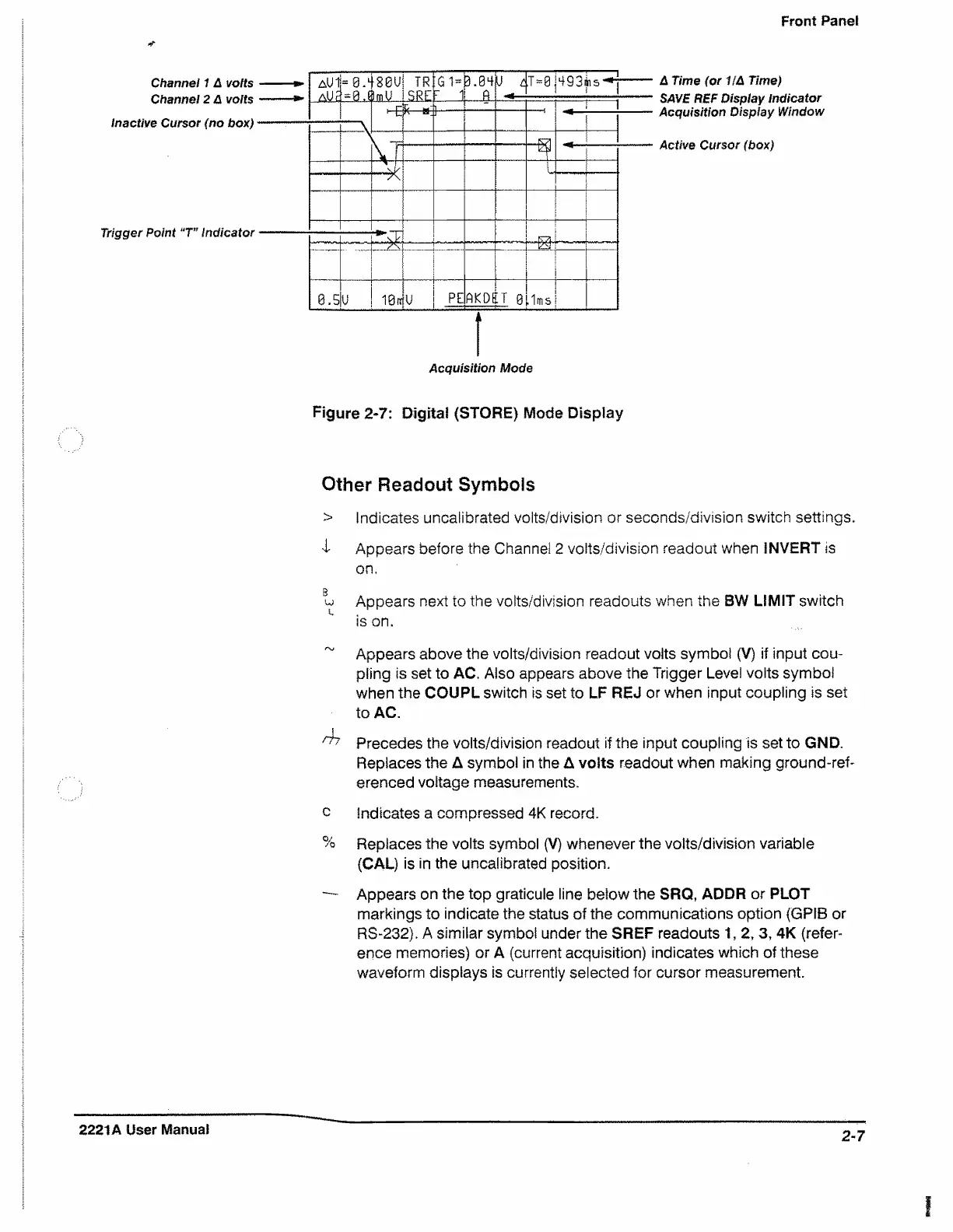
Channel 1 A volts
Channel 2 A volts
Inactive Cursor (no box)
Trigger Point "T” Indicator
A Time (or HA Time)
SAVE REF Display Indicator
Acquisition Display Window
Active Cursor (box)
Figure 2-7: Digital (STORE) Mode Display
Other Readout Symbols
> Indicates uncalibrated volts/division or seconds/division switch settings.
I Appears before the Channel 2 voits/division readout when INVERT is
on.
g
uj Appears next to the volts/division readouts when the BW LIMIT switch
is on.
~ Appears above the volts/division readout volts symbol (V) if input cou
pling is set to AC. Also appears above the Trigger Level volts symbol
when the COUPL switch is set to LF REJ or when input coupling is set
to AC.
!
^ Precedes the voits/division readout if the input coupling is set to GND.
Replaces the A symbol in the A volts readout when making ground-ref
erenced voltage measurements.
c Indicates a compressed 4K record.
% Replaces the volts symbol (V) whenever the volts/division variable
(CAL) is in the uncalibrated position.
— Appears on the top graticule line below the SRQ, ADDR or PLOT
markings to indicate the status of the communications option (GPIB or
RS-232). A similar symbol under the SREF readouts 1, 2, 3, 4K (refer
ence memories) or A (current acquisition) indicates which of these
waveform displays is currently selected for cursor measurement.
2221A User Manual
2-7

 Loading...


