Displaying Signals
□ Step 4: Connect the probe tip to the signal source.
□ Step 5: Wait several seconds for the input-coupling capacitor to charge
to the DC level of the signal source.
□ Step 6: Set the input coupling switch to AC. Position the AC signal
within the graticule area.
Building a Basic
Display
Displaying a simple, repetitive signal is one of the most common tasks
encountered when using an oscilloscope. To properly display a signal you
must make the appropriate control settings in four different sections of the
front panel;
* CRT Display
* Vertical
a Horizontal
■ Trigger
These control sections are arranged left to right across the front panel of the
2221A Digital Storage Oscilloscope.
Presetting the Controls
It is often helpful to preset the front pane! controls to get a sweep on the
screen before you try to apply a signal. With a simple “trace” on screen you
can adjust the display intensity and focus before you make any other set
tings.
If you are unfamiliar with oscilloscopes you may want to begin with the basic
analog setup given in Start Up, page 1-4. in addition, the following sections
describe the basic controls and a general approach to setting them:
* Selecting the Display Mode (STORE/NON-STORE)
■ Selecting the Trigger Mode
a Selecting the Horizontal Mode and Scale
a Selecting the Vertical Mode and Scale
a Setting the Display Intensity and Focus
a Finding “Lost” Displays
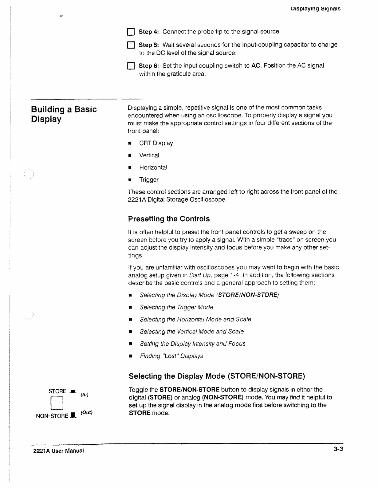
STORE
□
NON-STORE
On)
(Out)
Selecting the Display Mode (STORE/NON-STORE)
Toggle the STORE/NON-STORE button to display signals in either the
digital (STORE) or analog (NON-STORE) mode. You may find it helpful to
set up the signal display in the analog mode first before switching to the
STORE mode.
2221A User Manual
3-3