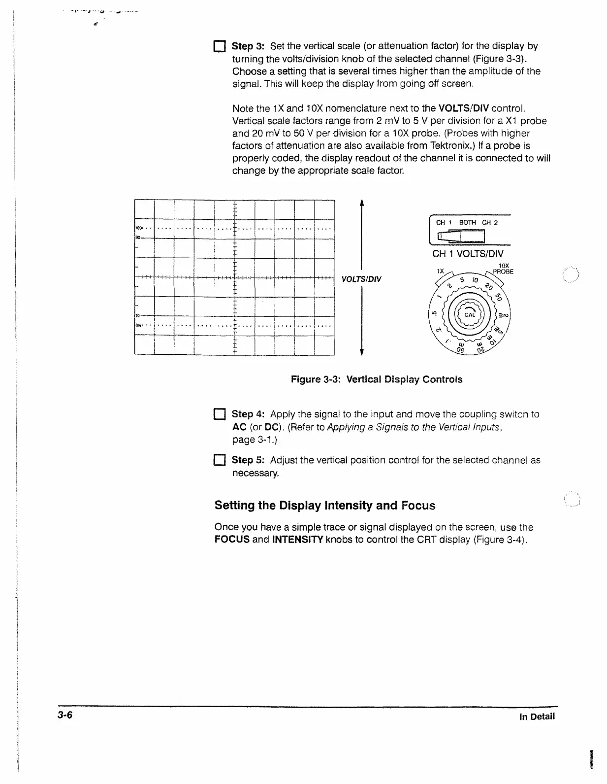
n Step 3: Set the vertical scale (or attenuation factor) for the display by
turning the volts/division knob of the selected channel (Figure 3-3).
Choose a setting that is several times higher than the amplitude of the
signal. This will keep the display from going off screen.
Note the IX and 10X nomenclature next to the VOLTS/DiV control.
Vertical scale factors range from 2 mV to 5 V per division for a XI probe
and 20 mV to 50 V per division for a 10X probe. (Probes with higher
factors of attenuation are also available from Tektronix.) If a probe is
properly coded, the display readout of the channel it is connected to will
change by the appropriate scale factor.
T
i
T
; t
-
r
......
..
1
-------------
1
I
i ’ i , ■ t ■ T i - 11
—
-
I
-
+
t 1
1
!
\
T
I i
it
VOLTS/DIV
r
CH 1
BOTH CH 2
\
_
_ E
J
CH 1 VOLTS/DIV
1GX
Figure 3-3: Vertical Display Controls
I~1 Step 4: Apply the signal to the input and move the coupling switch to
AC (or DC). (Refer to Applying a Signals to the Vertical inputs,
page 3-1.)
i~1 Step 5; Adjust the vertical position control for the selected channel as
necessary.
Setting the Display Intensity and Focus
Once you have a simple trace or signal displayed on the screen, use the
FOCUS and INTENSITY knobs to control the CRT display (Figure 3-4).
3-6
In Detail

 Loading...


