Displaying signals
«!f
n Step 2: Apply the TV signal to a channel input and display the channel.
□ Step 3: Set the VOLTS/DIV switch to display 2.5 divisions or more of
composite video signal.
f~l Step 4: Set the TRIGGER SLOPE switch either out (for positive-going
TV signal sync pulses) or in (for negative-going TV signal sync pulses).
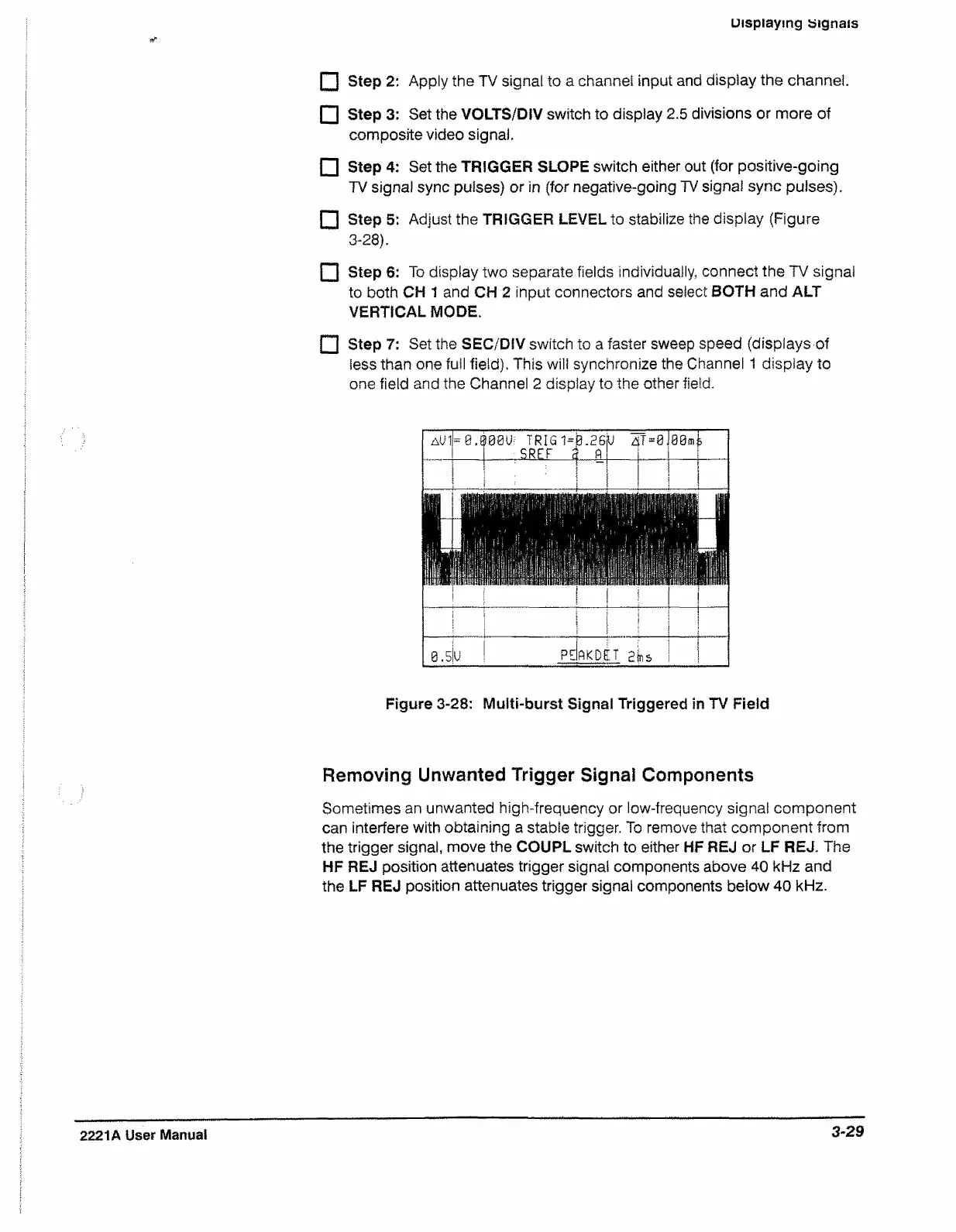
Step 5; Adjust the TRIGGER LEVEL to stabilize the display (Figure
3-28).
PI Step 6: To display two separate fields individually, connect the TV signal
to both CH 1 and CH 2 input connectors and select BOTH and ALT
VERTICAL MODE.
P I Step 7: Set the SEC/DIV switch to a faster sweep speed (displays of
less than one full field). This will synchronize the Channel 1 display to
one field and the Channel 2 display to the other field.
a U I -e.^ 08 U i TRIG 1=
| 5REF a
0.26
R
U d
T-0 J00m£
1 !
i
| i
i 1
\
I
LO
CD
u P E
A K D E T 2 b s
Figure 3-28; Multi-burst Signal Triggered in TV Field
Removing Unwanted Trigger Signal Components
Sometimes an unwanted high-frequency or low-frequency signal component
can interfere with obtaining a stable trigger. To remove that component from
the trigger signal, move the COUPL switch to either HF REJ or LF REJ. The
HF REJ position attenuates trigger signal components above 40 kHz and
the LF REJ position attenuates trigger signal components below 40 kHz.
2221A User Manual
3-29

 Loading...


