Appendix C: Performance Verification
Procedure Steps:
Q Step 1: Check internal Triggering
a. Connect the leveled sine wave generator output via a 50 Q cable
and a 50 Q termination to the CH 1 OR X input connector,
b. Set the generator to produce a 10 MHz, 3.5 division display.
c. Set the CH 1 VOLTS/DiV switch to 50 mV.
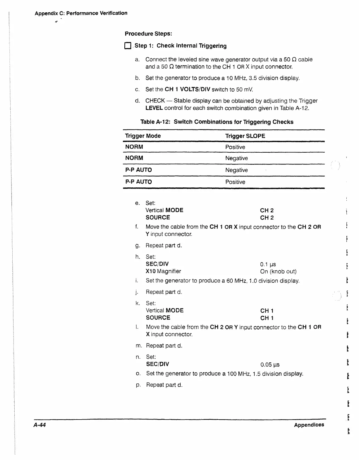
d. CHECK — Stable display can be obtained by adjusting the Trigger
LEVEL control for each switch combination given in Table A-12.
Table A-12: Switch Combinations for Triggering Checks
Trigger Mode
Trigger SLOPE
NORM
Positive
NORM
Negative
P-P AUTO
Negative
P-P AUTO
Positive
e. Set:
Vertical MODE CH 2
SOURCE CH 2
f. Move the cable from the CH 1 OR X input connector to the CH 2 OR
Y input connector.
g. Repeat part d.
h. Set:
SEC/DiV 0.1 ps
X I0 Magnifier On (knob out)
i. Set the generator to produce a 60 MHz, 1.0 division display.
j. Repeat part d.
k. Set:
Vertical MODE CH 1
SOURCE CH 1
l. Move the cable from the CH 2 OR Y input connector to the CH 1 OR
X input connector.
m. Repeat part d.
n. Set:
SEC/DiV 0.05 ps
o. Set the generator to produce a 100 MHz, 1.5 division display.
p. Repeat part d.
A-44
Appendices

 Loading...


