Measuring Signals
C l Step 2: Using either probes or coaxial cables with equal time delays,
connect a known reference signal to the Channel 1 input and the un
known signal to the Channel 2 input.
f l Step 3: Switch the Vertical Mode to BOTH and then select either ALT or
CHOP
H Step 4: Set both VOLTS/DIV switches and both variable controls so the
displays are equal in amplitude.
f l Step 5: Set the SOURCE to CH 1 so the oscilloscope uses only the
reference signal for triggering. Adjust the TRIGGER LEVEL control for a
stable display.
f l Step 6: Set the SEC/DIV switch to a sweep speed that displays about
one full cycle of the reference waveform.
f~l Step 7: Position the displays and adjust the SEC/DIV variable control so
that one cycie of the reference signal occupies exactly 8 horizontal
divisions. Each horizontal division of the graticule now represents 45° of
the cycle (360° 8 divisions).
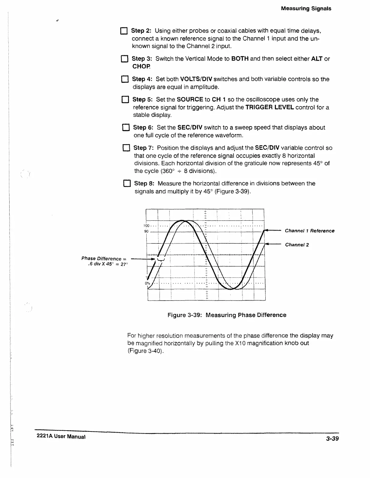
F l Step 8: Measure the horizontal difference in divisions between the
signals and multiply it by 45° (Figure 3-39).
Channel 1 Reference
Channel 2
Figure 3-39: Measuring Phase Difference
For higher resolution measurements of the phase difference the display may
be magnified horizontally by pulling the XI0 magnification knob out
(Figure 3-40).
2221A User Manual
3-39