M fjfjcrtufx d ; o peu inu auuri
**■
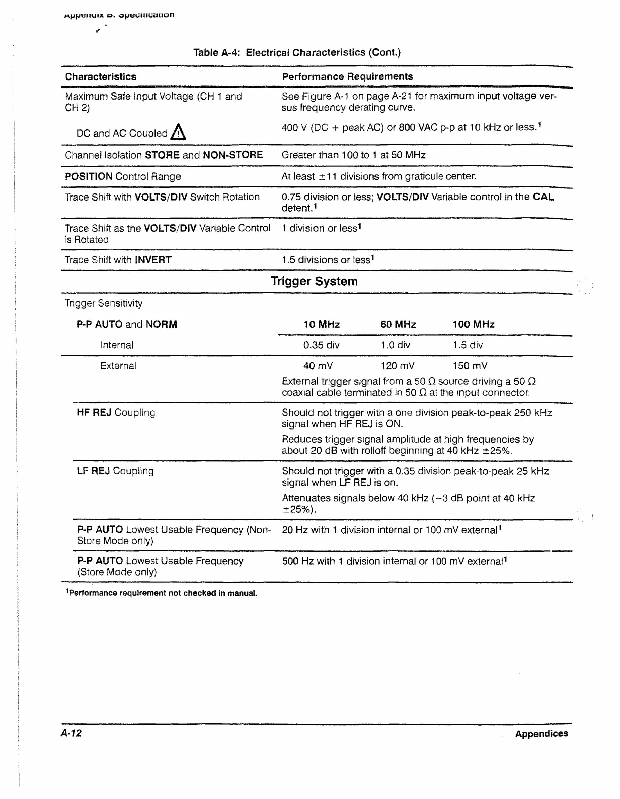
Table A-4: Electrical Characteristics (Cont.)
Characteristics Performance Requirements
Maximum Safe Input Voltage (CH 1 and
CH 2)
See Figure A-1 on page A-21 for maximum input voltage ver
sus frequency derating curve.
DC and AC Coupled ^
400 V (DC + peak AC) or 800 VAC p-p at 10 kHz or less.1
Channel Isolation STORE and NON-STORE
Greater than 100 to 1 at 50 MHz
POSITION Control Range
At least ±11 divisions from graticule center.
Trace Shift with VOLTS/DIV Switch Rotation 0.75 division or less; VOLTS/DIV Variable control in the CAL
detent.1
Trace Shift as the VOLTS/DIV Variable Control
is Rotated
1 division or less1
Trace Shift with INVERT 1.5 divisions or less1
Trigger System
Trigger Sensitivity
P-P AUTO and NORM 10 MHz 60 MHz 100 MHz
Internal
0.35 div 1.0 div 1.5 div
Externa!
40 mV 120 mV 150 mV
External trigger signal from a 50 O source driving a 50 Q
coaxial cable terminated in 50 Q at the input connector.
HF REJ Coupling
Should not trigger with a one division peak-to-peak 250 kHz
signal when HF REJ is ON.
Reduces trigger signal amplitude at high frequencies by
about 20 dB with rolloff beginning at 40 kHz ±25%.
LF REJ Coupling
Should not trigger with a 0,35 division peak-to-peak 25 kHz
signal when LF REJ is on.
Attenuates signals below 40 kHz (-3 dB point at 40 kHz
±25%).
P-P AUTO Lowest Usable Frequency (Non-
Store Mode only)
■ 20 Hz with 1 division internal or 100 mV external1
P-P AUTO Lowest Usable Frequency
(Store Mode only)
500 Hz with 1 division internal or 100 mV external1
Performance requirement not checked in manual.
A-12
Appendices

 Loading...


