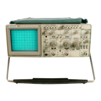
from panel
&
6. COUPL
7.
Selects the method of coupling the trigger source:
NORM (Normal Coupling) — Couples all frequency components of the
trigger signal.
HF REJ (High-frequency Reject) — Attenuates AC components of the trig
ger signal above 40 kHz.
LF REJ (Low-frequency Reject) — Attenuates AC components of the trigger
signal below 40 kHz.
LINE SOURCE — Uses a signal derived from the AC power line to trigger
the sweep.
SOURCE
Selects the trigger signal source:
VERT MODE (Vertical Mode) -—The selected vertical mode automatically
supplies the trigger signal. In ADD or CHOP the trigger source is the alge
braic sum of the Channel 1 and Channel 2. In ALT, the trigger source alter
nates between the channels in sync with the display.
CH 1 — Selects only the signal in channel 1 as the trigger source regardless
of the vertical mode selected.
CH 2 — Selects only the signal in channel 2 as the trigger source.
EXT (External) — Uses the signal applied to the EXT INPUT connector as
the trigger signal.
8. LEVEL
Selects the voltage level on the positive (or negative) signal transition) at
which the trigger will occur.
9.
slo p e
Selects either the positive (button out) or the negative (button in) signal
transition for triggering the next sweep or acquisition.
10. SGLSWP
(Single Sweep) — Sets the oscilloscope to trigger a single sweep in the
NON-STORE mode. In the STORE mode, single-shot events are captured
and displayed.
2221A User Manual
2-19

 Loading...