Displaying Signals
Displaying Signals describes the basic tasks involved in using the
2232
Digital Storage Oscilloscope to reveal the waveform characteristics of electri-
cal signals. In particular, Building a Basic Display, provides an overview of
the control sections and is
a
good starting point for anyone unfamiliar with
oscilloscopes.
Applying Signals to
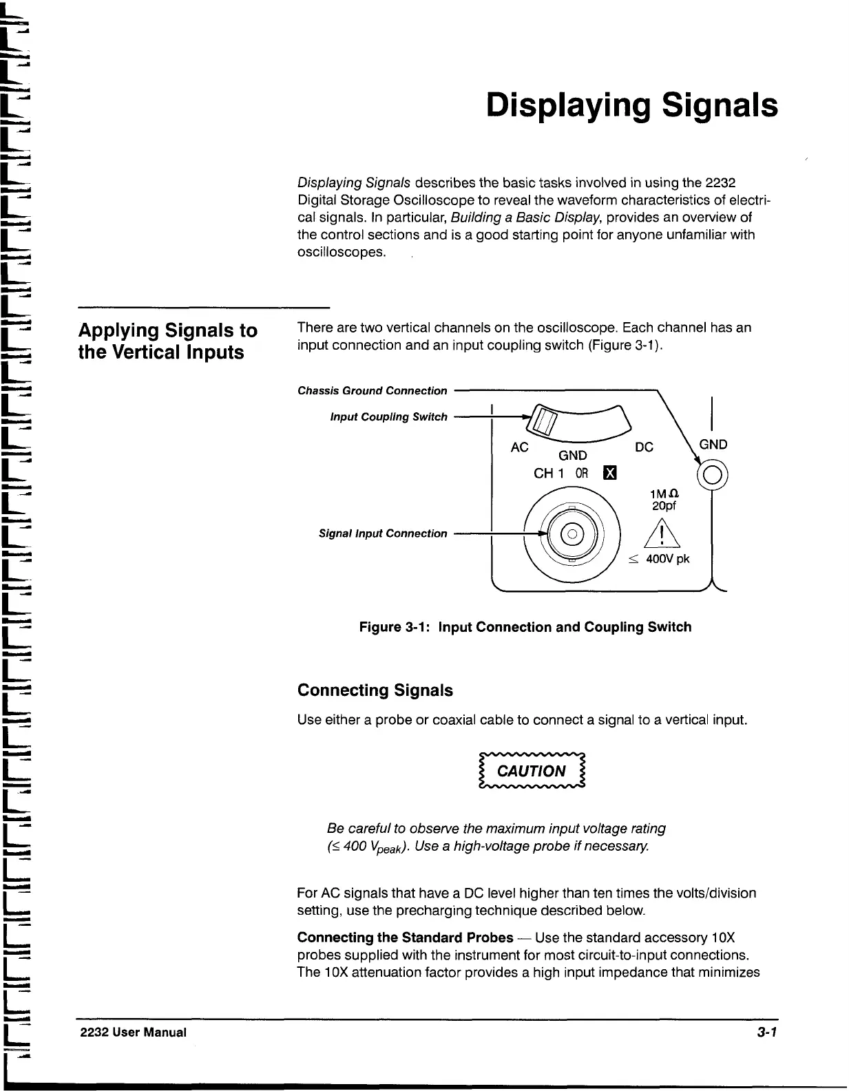
There are two vertical channels on the oscilloscope. Each channel has an
the Vertical Inputs
input connection and an input coupling switch (Figure
3-1).
Chassis Ground Connection
lnput Coupling Switch
Signal lnput Connection
-
GND
CH
1
OR
fl
I
400V
pk
Figure
3-1:
lnput Connection and Coupling Switch
Connecting Signals
Use either a probe or coaxial cable to connect a signal to a vertical input.
Be careful to observe the maximum input voltage rating
(S
400
Vpeak).
Use a high-voltage probe if necessary.
For
AC
signals that have a
DC
level higher than ten times the volts/division
setting, use the precharging technique described below.
Connecting the Standard Probes
-
Use the standard accessory
1
OX
probes supplied with the instrument for most circuit-to-input connections.
The
1
OX attenuation factor provides a high input impedance that minimizes
2232
User
Manual
3-
1
-
 Loading...


