Removal and Installation Procedures
6--22
TDS5000B Series Service Manual
assembly. See Figure 6--8, page 6--23. Note the pin 1 index mark on the
connector and the black stripe on the cable for later reassembly.
d. Pull the Front Panel assembly forward and remove from the oscilloscope.
4. Reinstallation: Do in reverse steps a through d to reinstall the Front Panel
assembly.
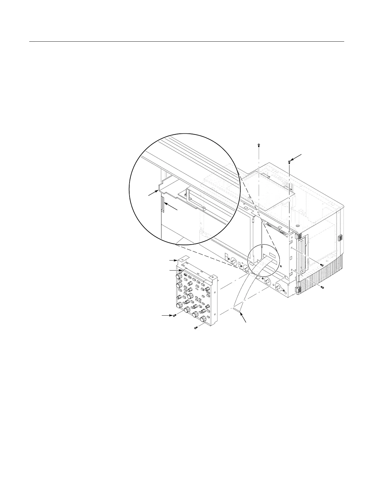
J1 ribbon cable
Front panel assembly
Front panel square
opening (2)
T--15 Torxdrive
screw (6)
Floppy disk
support tab
(2)
Chassis
slot (2)
T--15 Torxdrive
screw (4)
Figure 6--7: Front panel assembly removal

 Loading...


