Removal and Installation Procedures
TDS5000B Series Service Manual
6--27
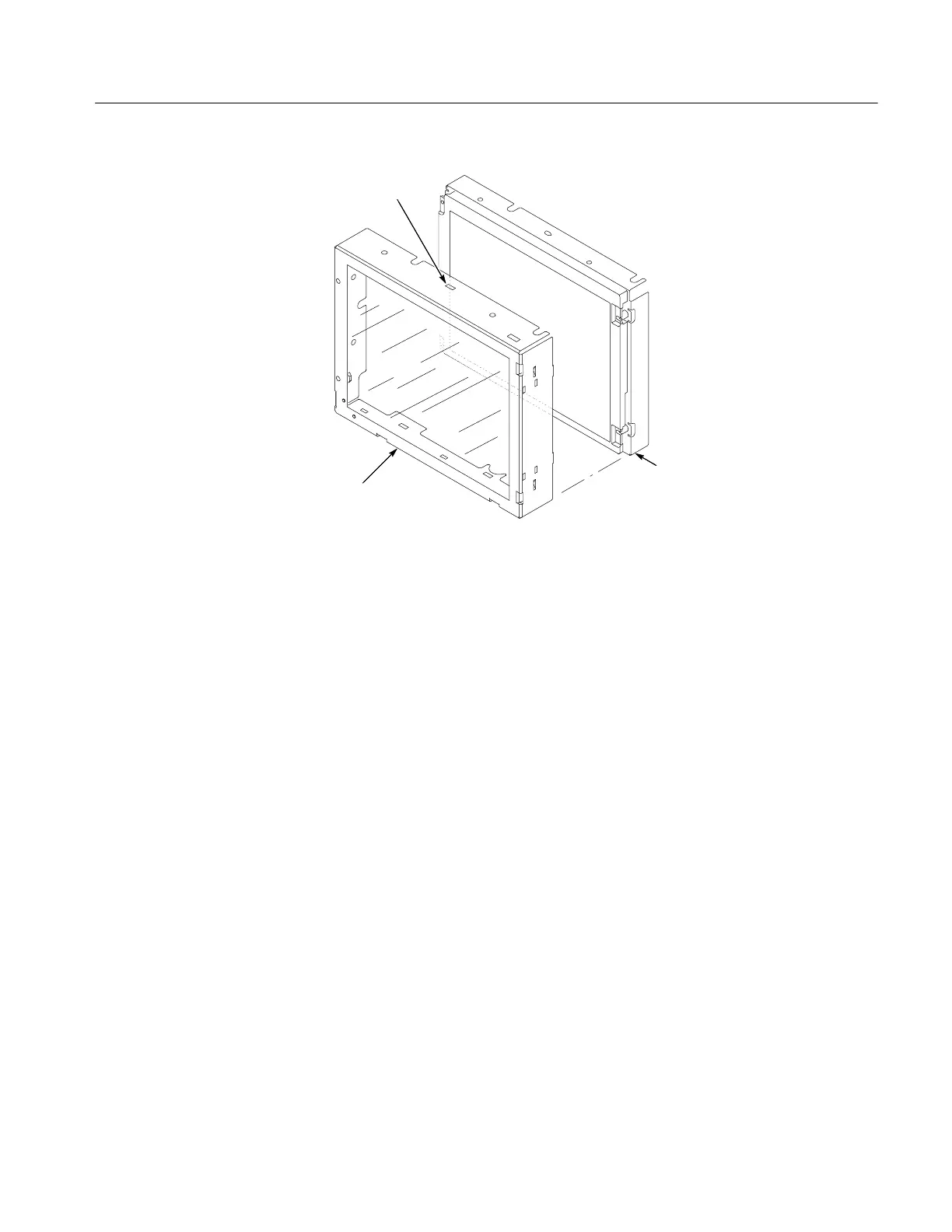
Touch panel
LCD module
Access notches
(top and bottom)
Figure 6--11: Touch panel and Display assembly removal
5. Reinstallation: Do in reverse steps 1 through 5 to reinstall the Display
assembly.
1. Locate module to be removed: Locate the display adapter board in the locator
diagram Internal Modules, Figure 6--6, on page 6--19. Additional modules to
be Removed:
H Trim (front panel & top)
H Display assembly
2. Remove the Display Adapter Board: See Figure 6--12, pages 6--28.
a. Disconnect cables J1, J6, J5, and J7 from the Display Adapter board.
b. Slide the connector clip, if present, off of J4.
c. Disconnect cable J4 from the Display Adapter board.
d. Remove the three T-15 Torxdrive screws that secure the Display Adapter
circuit board to the Display assembly. Remove the Display Adapter from
the assembly.
3. Reinstallation: Do in reverse steps a through d to reinstall the board.
Display Adapter Board

 Loading...


