Operating Information
2-8
TDS5000B Series Service Manual
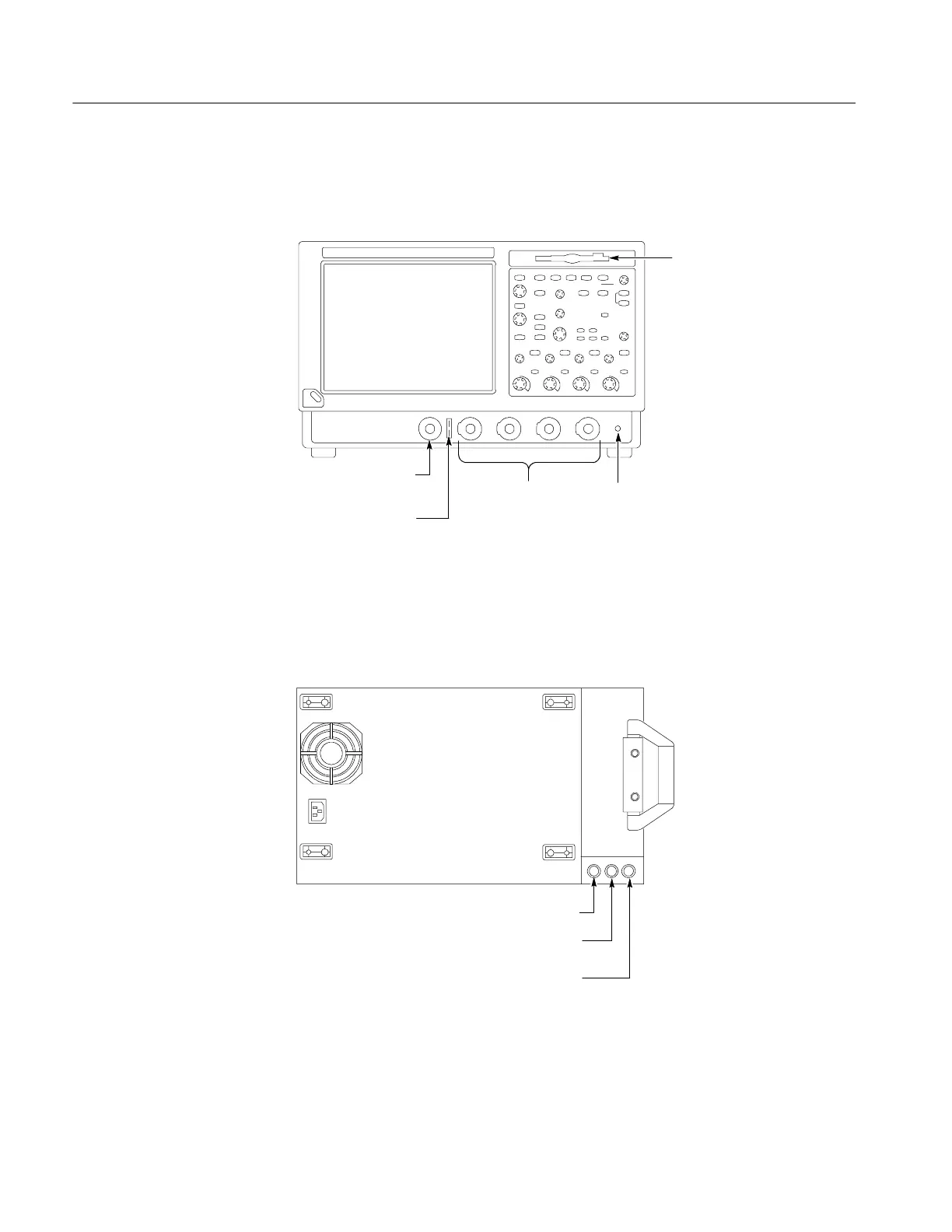
Figure 2--4 shows the input/output connectors and floppy disk drive location.
Floppy
disk drive
Auxiliary
trigger input
Probe comp output
Ground terminalChannel inputs
Front panel
Figure 2- 4: Locations of input/output connectors on the front panel
Figure 2--5 shows the input/output connectors on the rear panel.
AUX OUT
SIGNAL OUT
scale and offset controlled
by CH3 controls
EXT REF
Rear panel
Figure 2- 5: Locations of connectors on the rear panel
Front Panel I/O Map
Rear Panel I/O Map

 Loading...


