Troubleshooting
TDS5000B Series Service Manual
6-- 63
Troubleshooting Using Reset Circuits
The PC Interface board uses a combination of removable jumpers and test points
to manipulate circuit reset for troubleshooting.
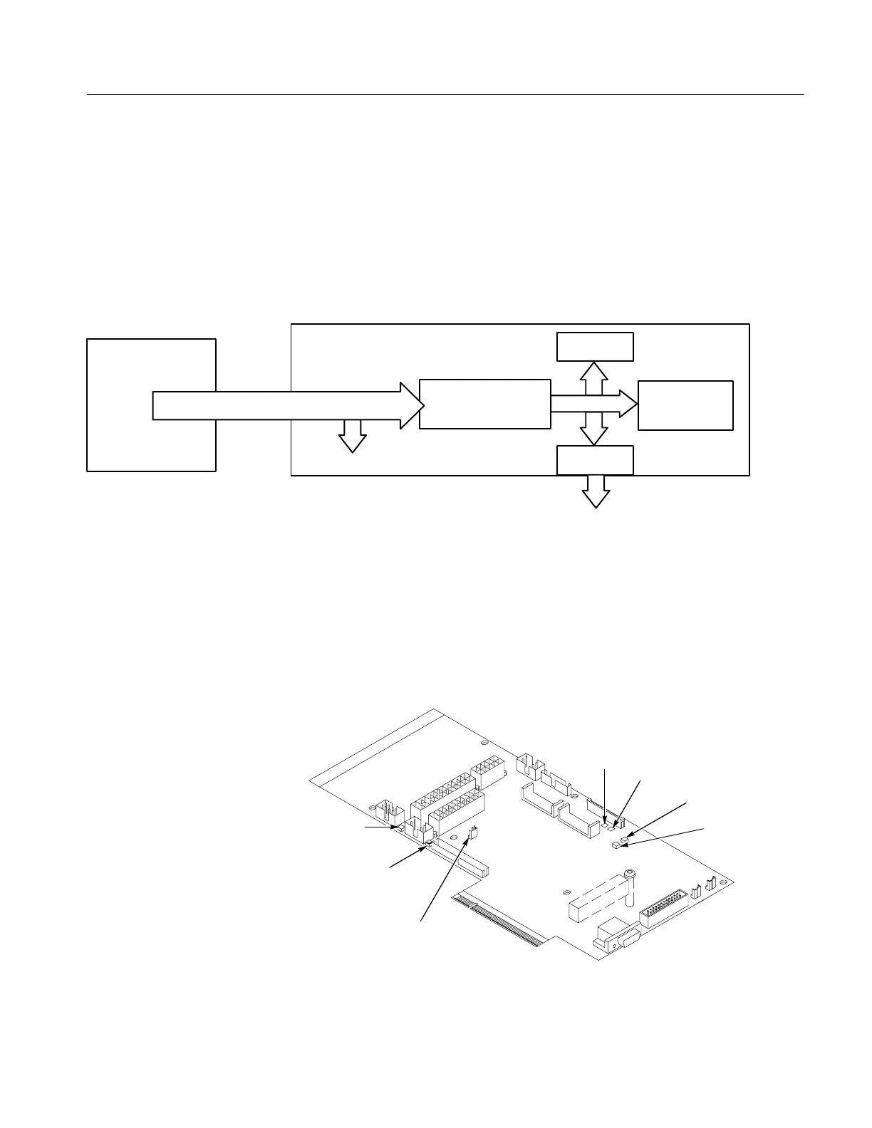
There are two PCI busses on the PC Interface board; the PC motherboard
primary PCI bus, and the L2 PCI bus. A hardware fault on any of these busses
can prevent Windows from starting properly.
69000 Video Adapter
J200
PC Interface Board
PCI Bus
Transparent Bridge
PC Motherboard
GPIB
I/O Processor
PAI
PA BusJ1020
Bus 2
Figure 6--28: The PCI busses
By grounding test points TP1102 or TP1103 (see Figure 6--29) you can selective-
ly remove components from the PC motherboard primary PCI bus. This is useful
when Windows will not start. The PC Interface board components on the PC
motherboard primary PCI bus are the 21152 transparent bridge, and the 69000
video adapter.
Reset button
TP1102
TP1103
JP1100 Forced
Power on
CR520
Hard disk
activity LED
CR710
PAI load
error LED
CR700
PAI loading
LED
Figure 6--29: Location of jumpers and reset button

 Loading...


