Removal and Installation Procedures
6--26
TDS5000B Series Service Manual
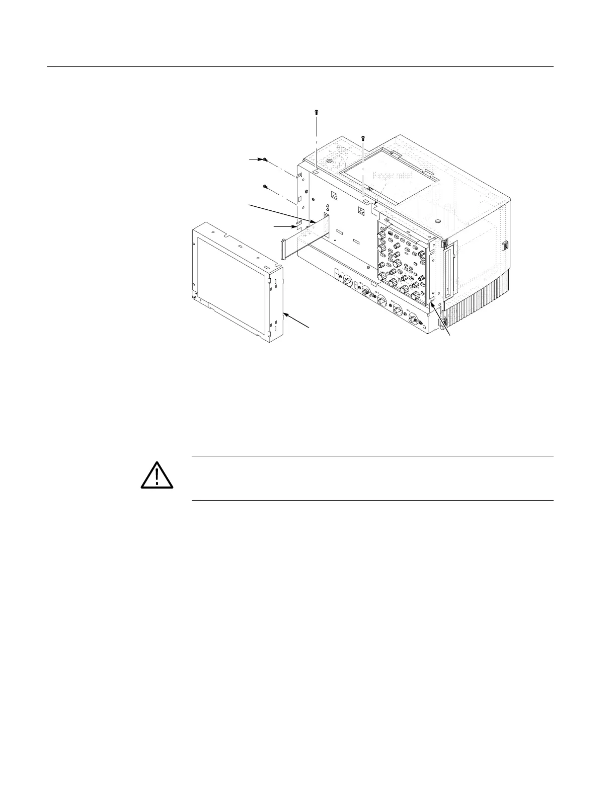
T-15 Torxdrive
screw (4)
Display
assembly
J5 Flex cable
Finger relief
Finger relief
Finger reliefFinger relief
Figure 6--10: Display removal
4. Remove the Touch panel from the Display assembly: See figures 6--11 and
6--12, on pages 6--27 and 6--28.
CAUTION. To prevent degradation of the display sharpness, this procedure must
be performed in a dust free environment. Wear cotton gloves to prevent finger
oils from contaminating any surfaces of the display glass.
a. Disconnect cables J1 and J7 from the Display Adapter circuit board.
b. Separate the assembly by carefully prying the (outer) Touch panel
assembly from the (inner) Display assembly. Insert a flat-bladed
screwdriver in the access notches to push out on the Touch panel
assembly.

 Loading...


