Removal and Installation Procedures
6--32
TDS5000B Series Service Manual
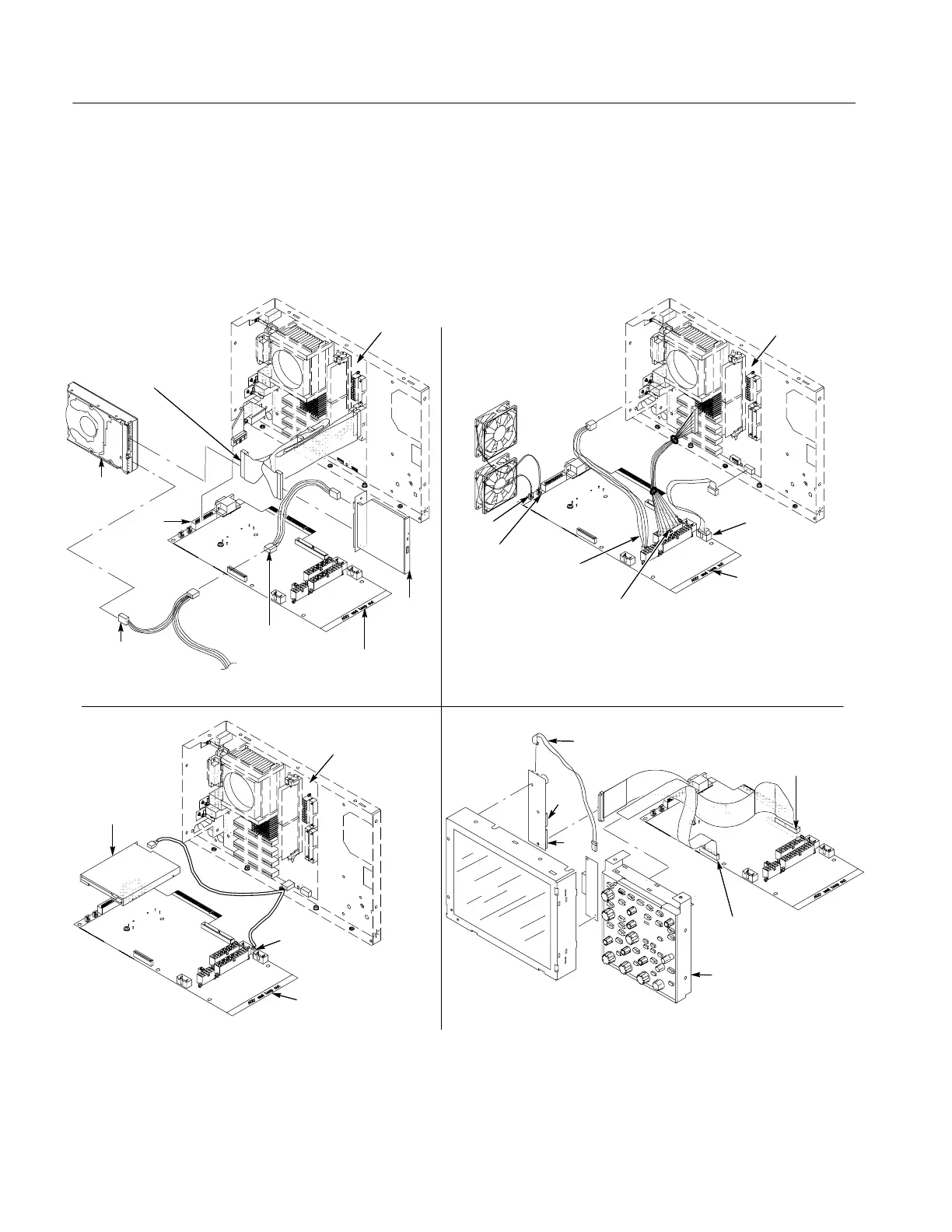
PC Interface Board and Motherboard Cable Connections
Figure 6--16 shows the location of cables and cable connectors for the PC
interface board and the motherboard. Pay close attention to this diagram and the
cable connections when you disassemble and reassemble the instrument.
J1040/Power
supply cable
J1401/CPU
power cable
J520/ATX
USB cable
J1060
J1070
PC interface
board
CDRW
drive
Hard drive
PC interface
board
Motherboard
HD and
CDRW cables
J510/CDRW drive
power cable
From power
supply
J510/CDRW drive
power cable
Front panel
assembly
J510/Front panel
PWR cable
J2
J3
J1010/Front
panel cable
Inverter
adapter cable
J1000/Dual
USB cable
Floppy disk
drive
Motherboard
PC interface
board
Motherboard
GPIB
J1600
Figure 6--16: PC Interface board and motherboard cable connections

 Loading...


