Removal and Installation Procedures
6--40
TDS5000B Series Service Manual
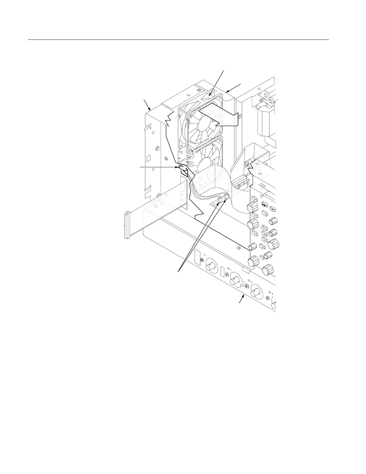
Fans
Fan cable
holder
Left side of the
instrument
Front of the
instrument
Back of the
instrument
Disconnect fan cables
Figure 6--21: Disconnecting the fan cables
1. Assemble equipment and locate modules to be removed: Locate the modules
to be removed in the locator diagram Internal Modules, Figure 6--6,
on page 6--19. Additional modules to be removed:
H Trim (all)
H Right side cover
2. Orient the oscilloscope: Set the oscilloscope so the bottom is down on the
work surface and the back is facing you.
Power Supply

 Loading...


