Removal and Installation Procedures
TDS5000B Series Service Manual
6--23
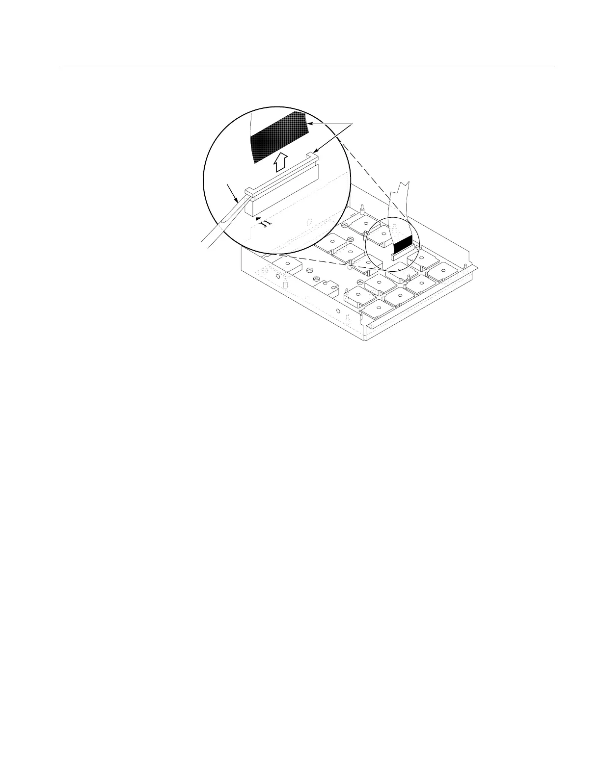
Screwdriver
Black stripe
toward connector
Figure 6--8: J1 flex cable connector removal
1. Locate module to be removed: Locate the Front Panel assembly Figure 6--7,
page 6--22. Additional modules to be removed:
H Front Panel Knobs
H Trim (front panel)
H Front Panel assembly
2. Remove the Front Panel board: See Figure 6--9, page 6--24.
a. Remove the eight T-15 Torxdrive screws that secure the Front Panel
board to the Front Panel assembly.
b. Pry the board up off the alignment studs. Place a flat -bladed s crewdriver
in the pry-point access holes to pry the board up from the assembly.
c. Remove the board from the assembly.
3. Reinstallation: Do in reverse steps a through c to reinstall the Front Panel
board.
Front Panel Board

 Loading...


