Removal and Installation Procedures
6--30
TDS5000B Series Service Manual
1. Locate modules to be removed: Locate the Floppy Disk Drive in the locator
diagram Internal Modules, Figure 6--6, page 6--19. Additional modules to be
removed:
H Trim (front panel)
H Cover (top)
2. Orient the oscilloscope: Set the oscilloscope so the bottom is down on the
work surface and the front panel is facing you.
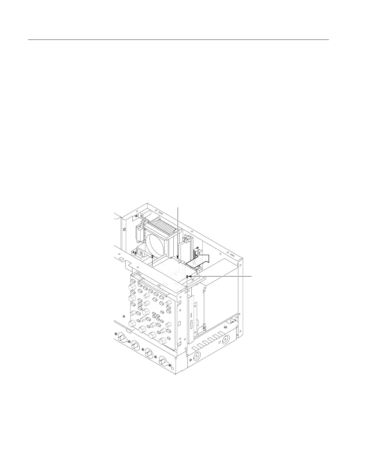
3. Remove the floppy disk drive: Use Figure 6--14 as a guide. A #0 Phillips
screwdriver is required for this procedure.
a. Remove the cable from the back of the floppy disk drive.
b. Remove the two T-15 Torxdrive screws that secure the floppy disk drive
assembly to the chassis.
T-15 T orx
screw (2)
Floppy drive cable
Figure 6--14: Floppy disk drive assembly removal
c. Remove the two small Phillips screws that secure the floppy disk drive
assembly to the bracket.
Floppy Disk Drive

 Loading...


