23
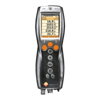
2 Tabs and tab info field:
• Tabs: Display of measuring system components (CU =
control unit, 2, 3, ... = analyzer boxes, analog output box)
connected to the control unit.
The tabs provide access to the individual components.
Warning symbol:
- Red frame, red symbol/white background:
Display of instrument errors in the instrument diagnosis
menu, otherwise: Instrument designation.
- Black frame, black symbol/yellow background:
Information message (symbol is displayed alternately with
the instrument designation).
- Yellow frame, yellow symbol/red background:
Warning (symbol is displayed alternately with the
instrument designation).
• Information field on tab (only in the tabs of analyzer boxes):
Indication of selected folder/measurement site, selected
fuel, chosen application, status of power supply and
remaining rech. batt. capacity (valid for analyzer box,
symbols like for display of control unit, see above), set
dilution factor.
3 Selection field for functions (chosen function appears against a
white background, unavailable functions are identified by grey
characters) or display of measuring values.
4 Function display for function keys.
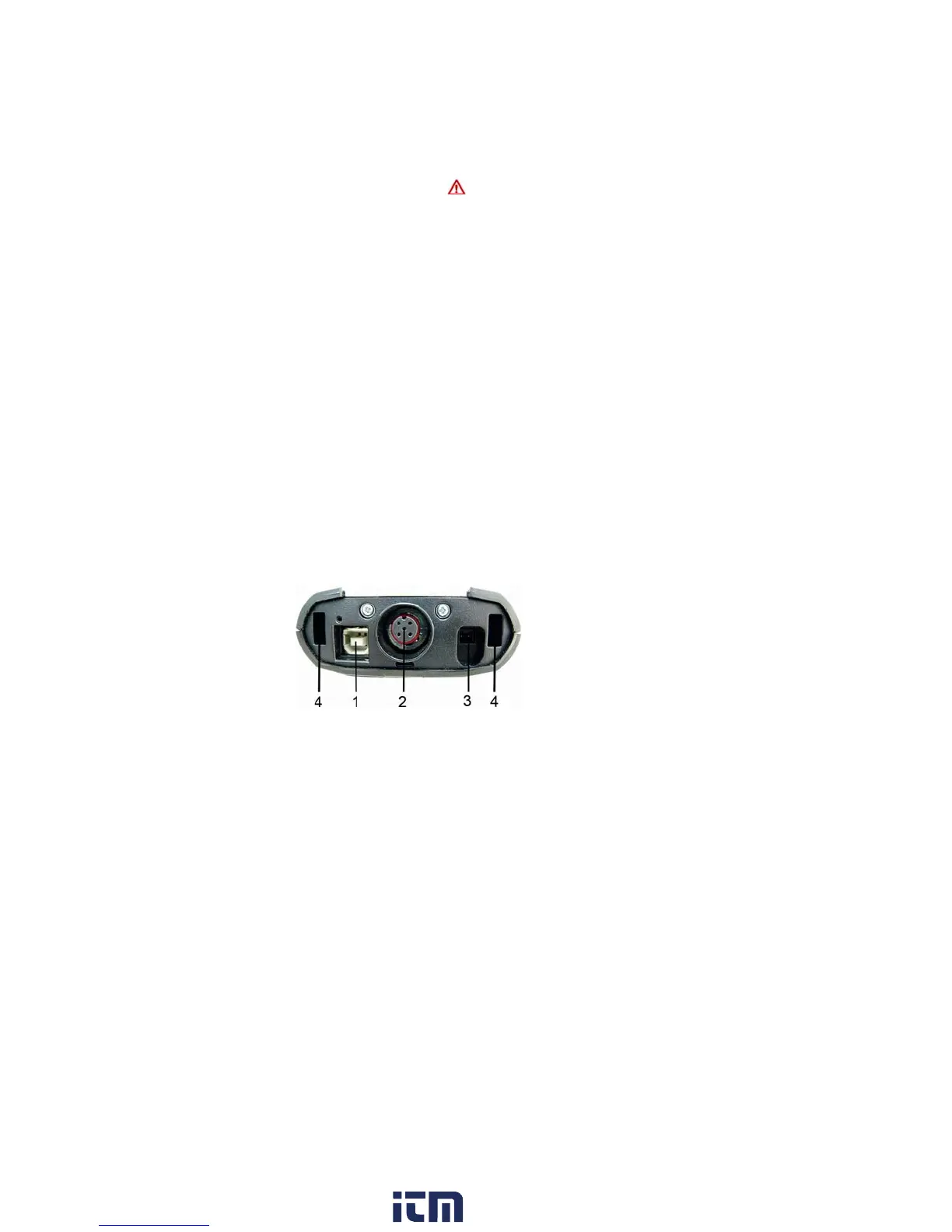
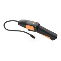
4.1.4. Connections / interfaces
1 USB 2.0
2 Testo data bus
3 Connecting socket for power supply 0554 1096
4 Guide groove for locking with analyzer box
w ww . . co m
information@itm.com1.800.561.8187