33
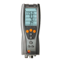
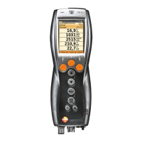
Control unit
1. Connect the plug of the power supply to the power supply
socket on the control unit.
2. Connect the plug of the power supply to an electiric socket.
- The control unit is powered by the power supply.
- If the control unit is switched off the rech. batt. charging process
will start automatically. Switching the control unit on has the
effect of stopping battery charging and the control unit being
powered via the power supply.
Analyzer box via internal power supply
> Connect the power cord to analyzer box.
- The analyzer box is powered via the internal power supply.
- If the analyzer box is switched off the rech. batt. charging
process will start automatically. Battery charging stops when the
flue gas analyzer is switched on by the control unit.
Analyzer box via DC-voltage input DC
✓ Cable with battery terminals and adapter for connection to
analyzer box required (0554 1337, accessory).
- If the analyzer box is switched off the rech. batt. charging
process will start automatically. Battery charging stops when the
flue gas analyzer is switched on by the control unit.
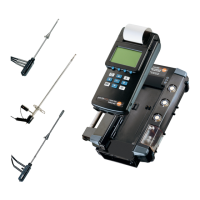
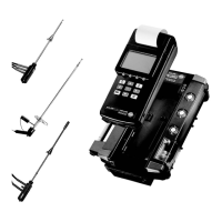
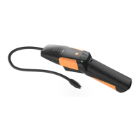
5.2.2. Connecting probes
Probe detection takes place during the activation
process: Probes that are required must always be
connected before the analyzer is switched on, or the
analyzer must be switched off and then on again after a
probe change, so that the correct sensor data can be
shown.
> Connect the required probes to the corresponding ports.
w ww . . co m
information@itm.com1.800.561.8187