81
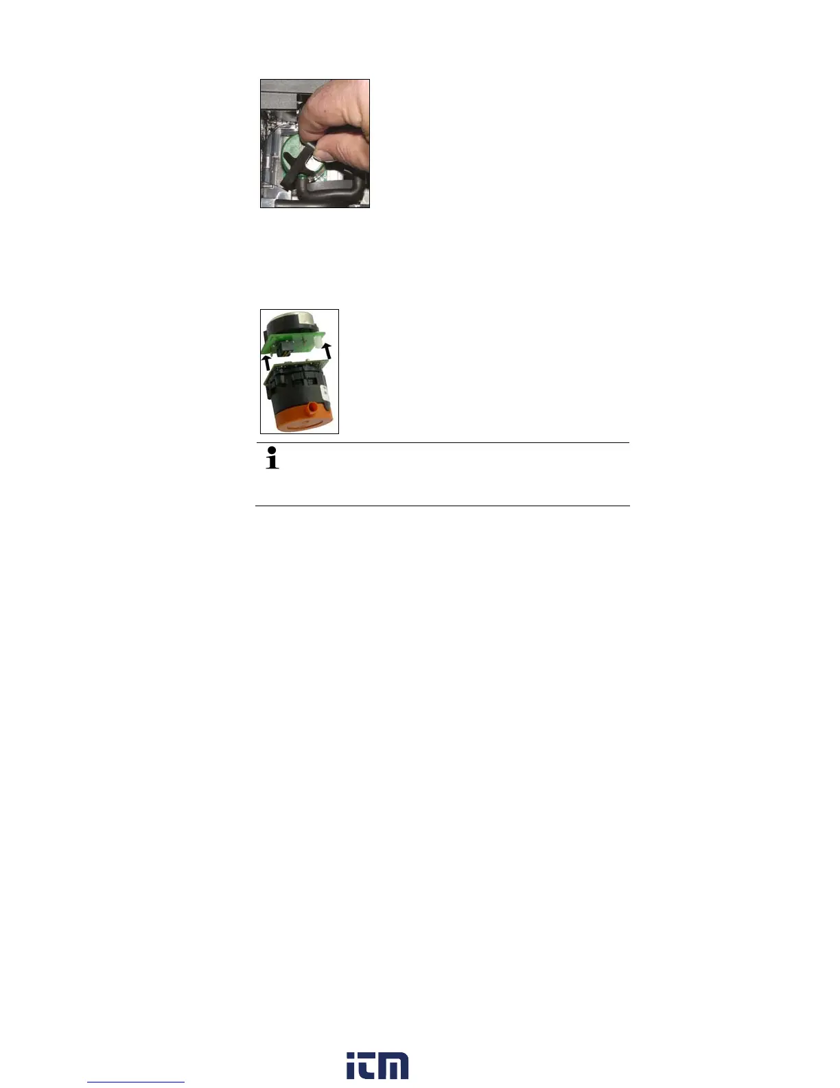
4. Take the sensor out of the bracket.
5. Pull the hose connections off the connecting nipples of the
defective sensor/the bridge.
6. Remove the defective sensor/bridge from the slot.
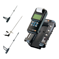
> NO- / NO
low
sensors: Remove the auxiliary circuit board.
Remove the additional circuit boards of the new sensors
just before the installation. Do not allow sensors to lay
around without additional circuit board for longer than
15min.
w ww . . co m
information@itm.com1.800.561.8187