SERVICE 5-32 Manual 0-4691
5
7. The thermal pad, provided with the replacement part, is a thin metal pad. Remove any loose protective paper coverings
from the pad.
NOTE
Protective coverings must be removed from the thermal pads. Installing thermal pads with protective coverings in
place will cause equipment damage or failure.
8. Install replacement components as follows:
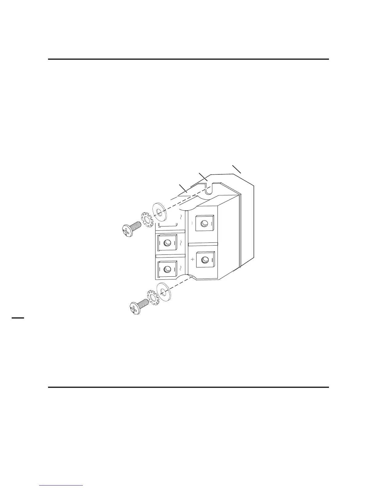
a. Apply the thermal pad to the flat surface of the bridge. Align the pad with the rectangular flat surface on the back of
the device.
b. Align the bridge with its mounting holes in the power supply chassis.
c. Secure the bridge and rectangular pad to the chassis with the replacement screws and washers.
Bridge
Thermal Pad
Art # A-04609
Power Supply
Center Chassis
Input Diode Replacement
9. Torque the diode mounting screws to 18 in-lb. (2.0 Nm).
NOTE
Failure to torque properly will cause component damage.