Troubleshooting
Board-Level Connection Diagrams
Thermo Electron Corporation Model 48i Instruction Manual 6-5
Board-Level
Connection Diagrams
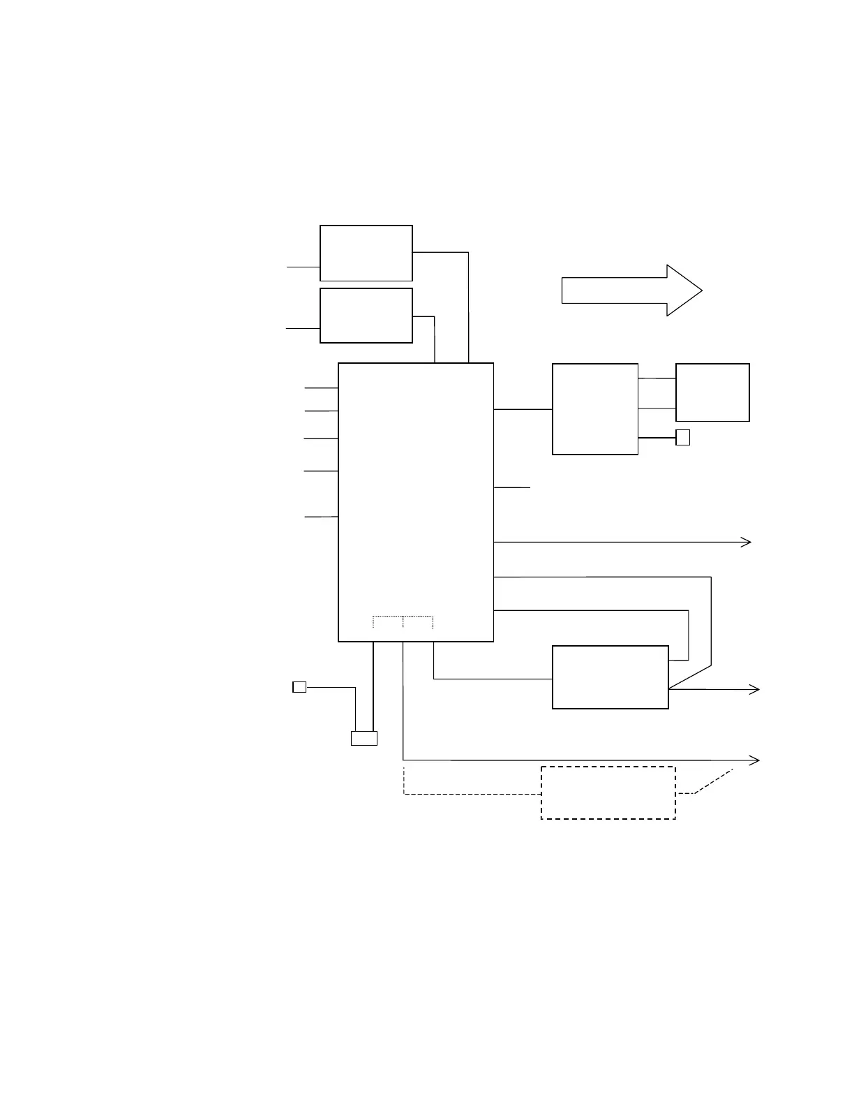
Figure 6-1 and Figure 6-2 are board-level connection diagrams for the
common electronics and measurement system. These illustrations can be
used along with the connector pin descriptions in Table 6-3 through
Table 6-8 to troubleshoot board-level faults.
Figure 6-1. Board-Level Connection Diagram - Common Electronics
2 Pin
P1
DIGITAL
OUTPUTS
24VDC
POWER
SUPPLY
MOTHER BOARD
DIGITAL OUTPUT
BOARD
I/O EXPANSION
BOARD
J14
J3
FRONT
PANEL
BOARD
J1
LCD
DISPLAY
KEY PANEL
J18
J2
J4
J3
J1
J10
J17
PJ1 PJ3 PJ2
FRON T PANEL
POW ER SW
16 Pin
4 Pin
8 Pin
34 Pin
3 Pin
2 Pin
3 Pin 3 Pin
3 Pin
PJ6
3 Pin
IPJ8
3 Pin
8 Pin
11 Pin
2 Pin
EXPANSION RS485
ANALOG OUTPUTS
/DIG ITA L IN PU TS
P1:A
P1:B
RS232/RS485
J210
-
BASE
-
T
J15
J5
15 Pin
8 Pin
37 Pin
9 Pi
n
9 Pin
RS232/RS485
J1
EX PA N SIO N I/O
J2
25 Pin
37 Pin
AC
AC
REAR PANEL
AC INPUT
3 Cond
AC
POWER_GOOD
24VDC
TRANSFORMER
(90VAC or 240VAC
OPTIONS)
J4
8 Pin
SPARE DATA
DATA
TO MEASUREMENT SYSTEM