InstallingHydraulicHosesandTubes(O-RingFaceSealFitting)
g221221
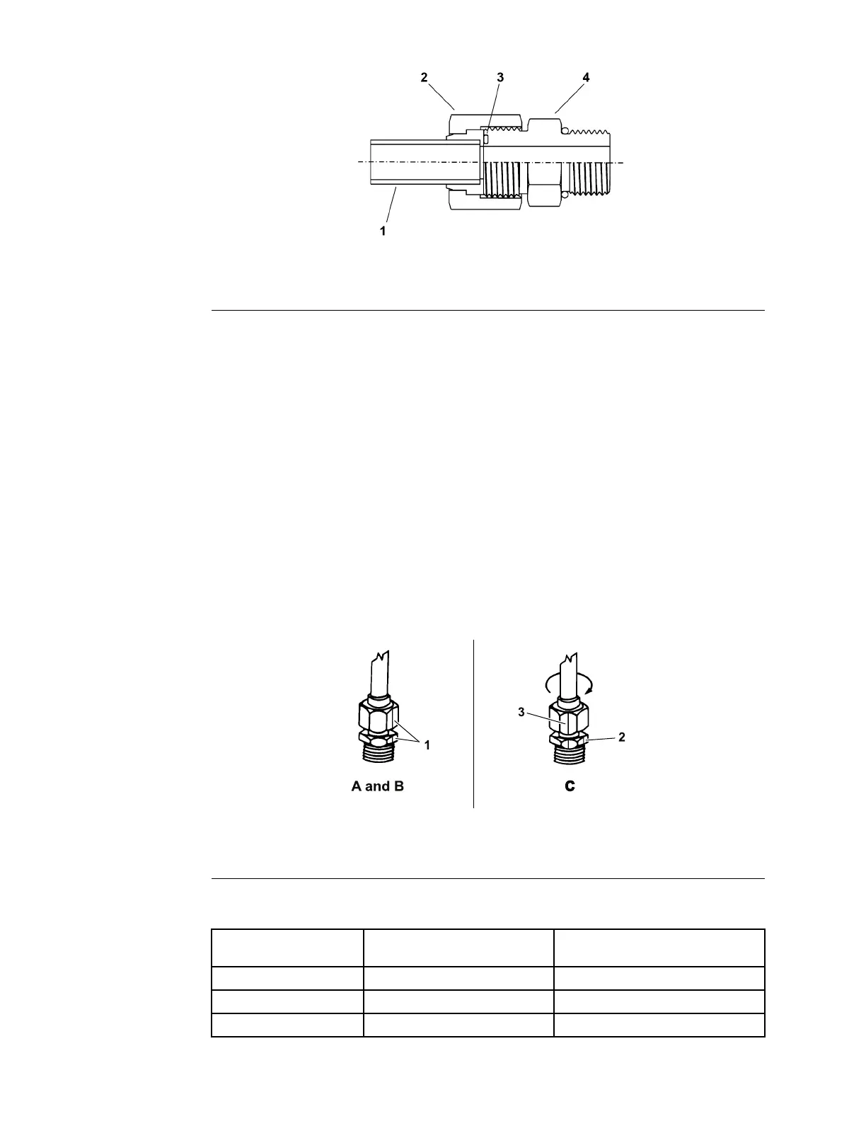
Figure19
1.Tubeorhose
2.Swivelnut3.O-ring
4.Fittingbody
1.Ensurethatallthethreads,thesealingsurfacesofthehose/tube,andthe
ttingarefreeofburrs,nicks,scratches,orunwantedmaterial.
2.Tohelppreventahydraulicleak,replacethefacesealO-ringwhenyouopen
theconnection.EnsurethattheO-ringisinstalledandcorrectlyseatedinthe
grooveofthetting.LightlylubricatetheO-ringwithcleanhydraulicuid.
3.Alignthehose/tubeagainstthebodyofthettingsothattheatfaceofthe
hose/tubesleevefullytouchestheO-ringinthetting(Figure19).
4.Useyourhandtothreadtheswivelnutontothetting.Whileyouholdthe
hose/tubeinalignmentwithawrench,useatorquewrenchtotightenthe
swivelnuttotherecommendedtorquevaluewithinthespeciedrangeof
torquevalues;refertotheHose/TubeInstallationT orqueT able(page5–8).
Thisproceduretotightentheswivelnutrequiresadrive-adapterwrench
(e.g.,crowfootwrench).
Note:Itmaybenecessarytouseadrive-adapterwrench(e.g.,crowfoot
wrench)toinstallahydraulictting;refertoCalculatingtheT orqueValues
WhenUsingaDrive-AdapterWrench(page2–6).
g212098
Figure20
1.Marknutandttingbody
2.Initialposition3.Finalposition
Hose/TubeInstallationTorqueTable
FittingDashSize
Hose/TubeSideThreadSize
(inch)—threadsperinch)
InstallationTorque
4
9/16—1824to27N∙m(18to20ft-lb)
6
11/16—1640to44N∙m(30to33ft-lb)
8
13/16—1654to59N∙m(40to44ft-lb)
HydraulicSystem:GeneralInformation
Page5–8
FieldPro®6040
22267SLRevA