Engine
g402342
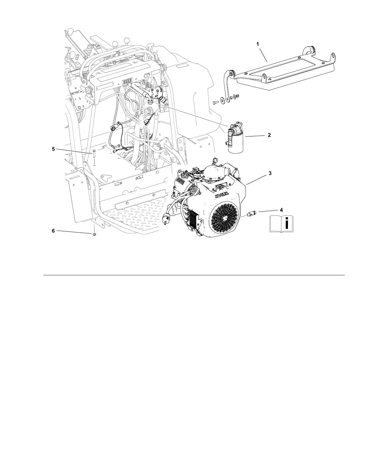
Figure15
1.Operatorcushionassembly
3.Engineassembly
5.Capscrew(4used)
2.Hydraulicuidlterassembly
4.Oildrainvalve6.Flangenut(4used)
RemovingtheEngine
RefertoFigure15forthisprocedure.
1.Disconnectthenegativebatterycablefromthebattery;refertoRemoving
andInstallingtheBattery(page6–29).
2.Removethepumpdrivebelttensioner;refertoRemovingthePumpDrive
BeltT ensioner(page4–18).
3.Removetheoperator’scushionassemblyfromthemachine.
4.Removetheaircleanerassembly;refertoRemovingandInstallingtheAir
Cleaner(page4–14).
5.Removethehydraulicuidcooler;refertoRemovingtheHydraulicFluid
Cooler(page5–59).
6.Cleantheareaaroundthehydraulichoseandttingconnectionsthen
disconnectorremovethehydraulichosesfromthehydraulicuidlter.Cap
orplugthedisconnectedhydraulichosesandttingstopreventhydraulic
systemcontamination.
7.Removethehydraulicuidlterassemblyfromthemachine.
FieldPro®6040
Page4–21
Engine:ServiceandRepairs
22267SLRevA